retrofit from stereo to s676a

5) On the left rear wheel arch within the boot area under the panels is a earthing point with mutiple slid on crimp points, just run the neg to this point with a spade crimp on it.
Is this below what you were talking about? This is a picture from the car with the 676, but no reason to think there is not one in the other car without 676 as I can see so many ground cable there.


Picture11.jpg

6) There is no ASD in the 35i, as per other reply. So that's why I sent you the diagram without the ASD in the line, so as to not confuse you ๐Ÿ˜‰
Some wiring colours did change over the years, alas you don't get this from NEWTIS diagrams. Don't worry about the colours, just compare the positions, that's the important point
Can I ask you how you know that the 35i does NOT have the ASD, I cannot manage to figure this out by looking at the newtis. :/ I Must say having a car with the 676 system I want to retrofit helps as I will basically mirror this into the other one.
But yes I am looking for consistency. Colours are just arbitrary.


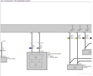
7) I realised that the footwell subs in the front left and right receive from the same pin at head unit. The cable split in door speaker and subwoofer at locations below, so I will cut the cable there I think and seize it. I will then connect the front subs to the wire coming from the amp. However, from the diagram it is clear the the front subs share the same channel. So I think that I will split the cables coming from pin 41 and 42 at amplifier level in two branches just in the boot. One which will go at left front sub, the other branch to the right front sub. This latter will probably be the only wire which I will pass through the driver side, as to avoiding butchering around the drive dashboard. Might be tricky.

Picture13.jpg
Picture14.jpg

8) Finally, I made a conversion sheet for the existing wiring (see below). I would appreciate if you would be able to go through it and cross compare it with the diagrams. It might take some time to go through it. Just an extra pair of eyes wont hurt ๐Ÿ˜Š

thank max.


Picture12.jpg
 
MaxSheperd said:
The one you found on ebay is for the top system 677,as it s got the tweeter; the 676 has the same support but without the tweeter. I removed the speaker, and as you can see below I placed the speaker in the bulkhead. I then bought the cover of the 677 rear central speaker which embeds the tweeter. The upper panel of the bulkhead goes in-between. There is no need for any support, since the speaker is screwed and the cover clips on the bulkhead.
Yeah, I know. My point was because you mentioned about "butchering" the dash to fit the centre speaker on top of the dash, I was trying to make the point that it is a straight swap. Yes it's from a 677 with the extra tweeter, but it doesn't matter as that tweeter plugs into the second hole of the midrange anyway, so makes no difference.


MaxSheperd said:
I have checked the z4 with the s676 and the connector is there and in pin number 5 where is what s coming from the amplifier in pin number 5 (thick 2.5 grey/read wire). So this is where the power supply will come through, I definitely think that the whole harness is passing by the passenger side. There is no reason to think it would jump through underneath the middle trim console or the driver side. I will see for when I have done the wiring as to where to pass everything through but passenger side via back of glovebox seems pretty good.

I have checked in the z4 without the s676, there is a connector, but I have not unplugged it as yet. I hope there will be a power supply for pin 5 which is where I m supposed to get the amp power supply. Will have to see this during the final butchering (glove box and central dashboard.
I was taking an educated guess as to where the particular loom would run, as I know there are looms both sides and down the centre. I would have gone for the passenger side as that is the side that the fusebox is on.
I would also presume that the plug will be in the bottom of the fusebox, but not the wire in location 5.

MaxSheperd said:
So if I can use any possible point the most handy I think would be the K_CAN_H in pin 11 and K_CAN_L in pin 30 of the connector found in the diagram X14271 (see below). I would basically cut the wires of pin 11 and pin 30 prior to reaching the connector X14271, then merge the wires coming from the centre information display with wire from pin 18 and 19 of the amp, then solder merged wires to the cable coming out of the connector X14271.
So basically
Pin 18 amp & wire from central information display (pin 3) >> K_CAN_H in pin 11 of X14271
Pin 19 amp & wire from central information display (pin 4) >> K_CAN_L in pin 30 of X14271
Would that work?
It would but it's a lot of running to do that. I think you've missunderstood what I was trying to say. There are various components directly in that particular canbus run, that includes...
Combox,
iDrive Controller,
Electrochromic Rear View Mirror,
FRM (Footwell Module),
FZD (Functional Control Centre, Roof),
Drivers Seat Module,
CAS,
Amplifier,
RDC (TPMS) *,
Comfort Access Control,
CTM (roof module) *,
Alarm Tilt Sensor,
PDC (Parking Sensor module) *.

Now some you may have and some you wont. The three I've marked with a * are good candidates, as they are in the boot area.


MaxSheperd said:
Ok this is not a biggy. From what you are saying it looks like it doesnโ€™t matter if I do not do it in the position shown above (X13887); I was thinking of connecting this cable from pin 10 of the amplifier to pin 1, as this is already receiving from the CIC anyway. As you said yourself.
Yeah making your connection at the Diversity module would be easy to find the wire, as opposed to breaking into the large loom

MaxSheperd said:
Is this below what you were talking about? This is a picture from the car with the 676, but no reason to think there is not one in the other car without 676 as I can see so many ground cable there.
Exactly the same as mine, and I don't have the amplifier at all! It is a standard earthing point.


MaxSheperd said:
Can I ask you how you know that the 35i does NOT have the ASD, I cannot manage to figure this out by looking at the newtis. :/ I Must say having a car with the 676 system I want to retrofit helps as I will basically mirror this into the other one.
But yes I am looking for consistency. Colours are just arbitrary.
Simple, none of the 6 cylindar engines had the ASD, it was solely there to make the 4 cylinders sound better to the driver. That's it, no other purpose. As previousley stated above, only the 18i, 20i and 28i (all 2ltr 4 cylinder engines) had the ASD, as the 23i, 30i, 35i and 35is are all 6 cylinders and sound better :fuelfire:


MaxSheperd said:
I realised that the footwell subs in the front left and right receive from the same pin at head unit. The cable split in door speaker and subwoofer at locations below, so I will cut the cable there I think and seize it. I will then connect the front subs to the wire coming from the amp. However, from the diagram it is clear the the front subs share the same channel. So I think that I will split the cables coming from pin 41 and 42 at amplifier level in two branches just in the boot. One which will go at left front sub, the other branch to the right front sub. This latter will probably be the only wire which I will pass through the driver side, as to avoiding butchering around the drive dashboard. Might be tricky.
Yep, agreed.


MaxSheperd said:
Finally, I made a conversion sheet for the existing wiring (see below). I would appreciate if you would be able to go through it and cross compare it with the diagrams. It might take some time to go through it. Just an extra pair of eyes wont hurt ๐Ÿ˜Š
Seems to be all in order.
Whereas it will be easier initially by joining the wires at the quadlock, might I suggest not doing it there and actually doing the following...
For the door speakers (both sides), join at the door jam connector.
Rear 1/4 midrange, join at the speaker.
I suggest this because you've got to run the new wire from the amplifier to these points anyway, and you've got to run new wires from the headunit to the amp, but doing it this way will save you a little and you won't have redundent sections of wire in the car.

Hope that all helps :thumbsup:
 
Hi, thanks for quick reply.
Centre speaker.
I have just realised that if I place it at the rear when I use the fading option in the CIC, and move the sound on the front, the โ€œrearโ€ speaker will go up along with the front speakers. It will basically become more like a boost_bass/normal_bass thing. Will have to try it and see how it feels.
Can low and high
I thought about the CTM then also thought did not want to mess with that, as I already soldered a new wire for the microswitch and already thinking about changing the hydraulic as over 10 year old. Thought best to leave CTM alone to its own problems.
I will use another one in the boot, I just thought I need to get to the fuse box anyway so could have been an option.

About wires:
My idea to join behind the head unit is because I am going to use the existing wires. But if I can easily find where the wire slits at locations below (behind the front subs), then I will join them there, but the existing wire will be left in the car unused. My idea was to use the existing wire through rather than adding more and leave some unused.

max

Picture14.jpgPicture13.jpg
 
The front centre speaker is an important part of the soundstage
Putting it in the rear will not help the audio staging
Since you canโ€™t code or adjust the 676 itโ€™s best to replicate the type and location of the speakers
But Iโ€™m sure you are aware of that
 
Sorry but there are no sensors for the positioning of the speakers. I could place the speaker as I see it fit, as long as find a way to fit them. The system cannot know.
Only when I will be playing it I will know if I like the way it sounds. I like sounds from the back, so I am positive and the top system has one there.
 
MaxSheperd said:
Hi, thanks for quick reply.
Centre speaker.
I have just realised that if I place it at the rear when I use the fading option in the CIC, and move the sound on the front, the โ€œrearโ€ speaker will go up along with the front speakers. It will basically become more like a boost_bass/normal_bass thing. Will have to try it and see how it feels.
Yeah agreed, there is little sound that comes from the rear anyway so I see what you are trying to achieve here. Like you say "see how it feels"

MaxSheperd said:
Can low and high
I thought about the CTM then also thought did not want to mess with that, as I already soldered a new wire for the microswitch and already thinking about changing the hydraulic as over 10 year old. Thought best to leave CTM alone to its own problems.
I will use another one in the boot, I just thought I need to get to the fuse box anyway so could have been an option.
At the end of the day it doesn't matter where you tap into the canbus as they are all connected. The places I said above are all on the original stream as the amplifier would be, but it can be any point, just no need to run more wire than you need to.

MaxSheperd said:
About wires:
My idea to join behind the head unit is because I am going to use the existing wires. But if I can easily find where the wire slits at locations below (behind the front subs), then I will join them there, but the existing wire will be left in the car unused. My idea was to use the existing wire through rather than adding more and leave some unused.
A couple of inches from the speaker plug is always a good point. This would give you an exact location and leave enough to solder the new (amplifier to speaker) wires to solder onto.

Reading what you are saying makes me think you are "over thinking" certain points. Try not to, keep it simple, if you run everything to the speaker location (or the door connector for the door speakers) then there is no chance to mix anything up.
 
MaxSheperd said:
The one you found on ebay is for the top system 677,as it s got the tweeter; the 676 has the same support but without the tweeter. I removed the speaker, and as you can see below I placed the speaker in the bulkhead....

Just going back to this....
It appears that the original speaker layout drawing may be wrong.

This image clearly shows that the front centre dash speaker doesn't have the additional tweeter for 676...
file.gif

Whereas this shot from the 676 wiring diagram clearly shows that it comes with the tweeter...

hi-fi.jpg

The diagram could be wrong, and someone was lazy in not bothering to delete it, but who knows :D
 

Attachments

  • hi-fi.jpg
    hi-fi.jpg
    57.6 KB · Views: 5,095
I think it s the diagram, since the support for the front central speaker behind the nav screen does NOT have the support for the tweeter, the is plastic blocking it, though obviously you can cut out with hot blade and put a tweeter, as the speaker allows you to jump the tweeter over.
the same apples for the 3/4 rear left and rightspeaker. there I will cut out the plastic and insert the tweeter, as speakers allow it and the layout is already predisposed, just need cutting plastic out to insert them.
 
Yeah I tend to agree with you Max, probably a mistake on their part.

But then I've found this, 2013 Z4 wiring diagram for the Hi-Fi system (676).
This one also shows the additional tweeter for the centre top dash on this 676 system - On this, and from the same manual I have, the diagram for the 677 is completely different layout, so not just a generic copy over.

Link due to it's physical size to be able to read it...
 
Hello,
RE: diagrams
maybe they did it one way then discontinued the other way.

Just an update about this mod:
1) Dave, I followed your advise and did not solder any wires behind the headunit. I actually took more advantage of the existing wiring and used it as much as could. Though still some of the wiring had to be done assuming inconceivable positions whilst soldering as to ensuring messing with the car as little as possible. Thank you <3
2) I have finished 95% of the wiring. Posting some pics at the end of this post. I still need to do the connector in the fuse box for the power supply. I bought an e90 fuse box, which I will use as dummy but still does have the same time of connector which I could not find anywhere. Also waiting for rear ยพ tweeters be delivered and the 42-pin connector be delivered.

Picture1.jpg


3) I am going to test the wiring; I ll check all the connections to the speakers using a pair of pin from the head unit (formerly powering a set of speakers, say 2 and 6), then I will use one speaker to check if all pins coming from the head unit are indeed sending audio.

Picture2.jpg


4) Dave, earlier, for the coding, you said: โ€œAs for coding you'd have code $676 to the VO with FA_WRITE to CAS and NFRM and then SG_CODEIREN to CIC.โ€ I remember I had to change the vehicle order (VO), but I was wondering if you could please give some more details/guidance on this. That would be pretty much appreciated!


5) About the door speakers + tweeter. I just wanted to double check. These originally were powered by the same wiring from the headunit. So basically one wire for left door tweeter and speaker and front sub and one wire for the set on the driver side (right); by the way the wiring for the driver side goes from the head unit to around the fuse box; at this point it then goes behind the whole dash board and pops back on the driverโ€™s side, pretty much where the right front sub is.
Now, since both front left and right subs are powered by the same channel from the amplifier, I cut and seized the branch of the wiring going to them originally and reconnected them with the wiring coming from the amplifier. So I will still use the existing wiring for left door tweeter and speaker and right door tweeter and speaker.


Thanks
I hope this can help someone for this mod or something else too

Max


PICS:
Aerial diversity. Created a Y sections which will now go to the amp. Did this just on top of the rear left wheel arch as there is big harness.

Picture3.jpg

CAN high and low; there were two pairs of wires one for the CTM and one for the parking distance sensor unit. Picked the latter as did not want to mess with the CTM. So used a multimeter with disconnected battery to make sure I was cutting the right pair. The wires were so thin and given the age of the car I thought they were going to crack or weaken. I decided to use surgical electrode needles to assess them. The Y section was done next to the amp so easy to connect to.

Picture4.jpg

Picture5.jpg

The rear ยพ speaker + tweeter was cut and extended to reach the amp, then from the amp I brought a couple of wires at this spot to reconnect speakers after audio s been boosted by the amp.

Picture6.jpg
Picture7.jpg
Picture8.jpg

The bulk of the job was at the fuse box. I removed the glove box and front dashboard for easy access but still soldering positions to assume were kind of inconceivable to sustain for long periods.
Picture9.jpg
Picture10.jpg
 
On the driver side, the only cable pair to pass through was the one for the front right sub. Didnโ€™t want to mess with the driver side of the dashboard.

Picture11.jpg

The colour of the wiring if sort of random. Only the thickness has a rationale (power supply thicker, subs thicker, inputs from headunit thinner etc). This is because I factored in that I could do some connections wrong, so I tagged all ends, so if one is wrong you can always replace the tags.

Picture12.jpg

Picture13.jpg

The sub connector soldered to the new wiring coming from the amplifier.

Picture14.jpg
 
MaxSheperd said:
4) Dave, earlier, for the coding, you said: โ€œAs for coding you'd have code $676 to the VO with FA_WRITE to CAS and NFRM and then SG_CODEIREN to CIC.โ€ I remember I had to change the vehicle order (VO), but I was wondering if you could please give some more details/guidance on this. That would be pretty much appreciated!

Hi Max,

If you jump to 40 minutes on this video I run through the coding process....


So hopefully that'll give you the info just use the code you need to :thumbsup:
 
Hello Dave,

thanks for your reply.
I did watch that days ago. So I wondered if I need to type is $676 instead of $609 as you do at running time
and do exactly as you do apart from that?

thanks

max
 
MaxSheperd said:
Hello Dave,

thanks for your reply.
I did watch that days ago. So I wondered if I need to type is $676 instead of $609 as you do at running time
and do exactly as you do apart from that?

thanks

max


Basically yes! In the video I'm adding 609 and 6VC because I'm adding tge iDrive system, but all you need to do is add the 676 as that is what you're adding. As I say add 676 to the VO then FA_WRITE to CAS and NFRM and SG_CODERIEN to CIC and that should be all you need :thumbsup:
 
Hello

Just wanted to give an update about this mod.

I have finally finished the retrofit and it all works as it should; as said earlier on I fitted the front central speaker in the bulkhead and once I have tried the system I realised this was a very good decision, since you really hear much more than when positioned behind the CIC display. Secondly it allows more types of audio profiles for when you use the fader settings (front/rear). Also the extra tweeter makes it all better; I fitted 2 more in the ยพ rear speaker location and the cover for the rear central speaker came with one anyway.

I must say the soldering had to be done in inconceivable positions if you want to make sure that you do not butcher the car too much, and even if you factor this in, there is still quite an amount of it. But for me it was worth it. I love it.
Just needs loads of patience.
Dave, I just wanted to ask you I followed literally by the letter your video about retrofitting the CIC just added $676 at the relevant point in the video. However the system was also working already BEFORE the coding. I am not sure how better works now or how worse was working earlier. But is there anyway to check through the CIC to actually check that it is coded for the 676? But from all I can see everything is working as it should.
I have also created a new topic by the way as we found a leak in the other car (not this one that had the 676 fitted) but the other one that has it already!
Oh dear! You finish one thing and something else comes our way right away!!
Best

Max


IMG_20230727_173832.jpgIMG_20230727_171826.jpgIMG_20230725_180634.jpgIMG_20230725_170752.jpgIMG_20230725_165847.jpgIMG_20230725_165843.jpgIMG_20230725_144955.jpg
IMG_20230722_142822.jpgIMG_20230722_142814.jpgIMG_20230721_145553.jpg
 
Well done Max :thumbsup:


MaxSheperd said:
...
Dave, I just wanted to ask you I followed literally by the letter your video about retrofitting the CIC just added $676 at the relevant point in the video. However the system was also working already BEFORE the coding. I am not sure how better works now or how worse was working earlier. But is there anyway to check through the CIC to actually check that it is coded for the 676? But from all I can see everything is working as it should.
...

So long as you've added 676 to the VO and then FA_Write to CAS & NFRM and SG_Codeiren to CIC then it'll be all OK :thumbsup:
The system will work anyway, it's just that there are certain parameters that are different for the amplifier driven system as opposed to the headunit driven original, so it should all sound very much the same, just with more power for the extra speakers that have been added (subs and centre speakers).

I have thought about doing this myself, but for shear cost reasons I think I'll go for the Vibe add-on amp that requires no additional wiring on my part. On the whole most parts are cheap enough, it's just obtaining the subwoofers that aren't cheap, for less money I can buy a brand new Vibe additional sub that matches the Vibe amp.
 
hello
thanks for your reply

long as you've added 676 to the VO and then FA_Write to CAS & NFRM and SG_Codeiren to CIC then it'll be all OK >> if this is what you do in your retrofit of the headunit system, then yes, I did that only did I change the $676 to add instead of the other code you add there.


if you want to retrofit the 676 there are good deals atm.

will message you in PM.
 
AnubisZed said:
Well done Max :thumbsup:


MaxSheperd said:
...
Dave, I just wanted to ask you I followed literally by the letter your video about retrofitting the CIC just added $676 at the relevant point in the video. However the system was also working already BEFORE the coding. I am not sure how better works now or how worse was working earlier. But is there anyway to check through the CIC to actually check that it is coded for the 676? But from all I can see everything is working as it should.
...

So long as you've added 676 to the VO and then FA_Write to CAS & NFRM and SG_Codeiren to CIC then it'll be all OK :thumbsup:
The system will work anyway, it's just that there are certain parameters that are different for the amplifier driven system as opposed to the headunit driven original, so it should all sound very much the same, just with more power for the extra speakers that have been added (subs and centre speakers).

I have thought about doing this myself, but for shear cost reasons I think I'll go for the Vibe add-on amp that requires no additional wiring on my part. On the whole most parts are cheap enough, it's just obtaining the subwoofers that aren't cheap, for less money I can buy a brand new Vibe additional sub that matches the Vibe amp.

Dave I have the factory standard subs with enclosures here should you want them, I can do a very good price if needed. But I would have to question going down this route, at the end of day you will have a factory standard system which is limited in performance and going the aftermarket route as I have done in mine will yield better results with less complicated install.
 
Silverstar said:
Dave I have the factory standard subs with enclosures here should you want them, I can do a very good price if needed. But I would have to question going down this route, at the end of day you will have a factory standard system which is limited in performance and going the aftermarket route as I have done in mine will yield better results with less complicated install.

Thank you :thumbsup:

See now this is my quandary, if I go the OE route, yes it's a lot of work in theory, but at the end of the day it's OE, which is what I like to see. But if I go down the aftermarket route using the Vibe amp then it's straightforward plug-n-play, a couple of tweaks and you're done. It's also hidden away so you don't see it, even the matching sub is under one of the seats (it's a slimline sub).
Now I don't have a big issue with my system since I retrofitted it all, in fact I think it's very good quality, my issue is when the roof is down I'd like to be able to hear it a little better, nothing too grand, just enough, after all I'm driving with the roof down so I'm not expecting it to be full beans clarity. With the roof up and playing good music mine is a very decent system with a good level of sound already, I can hear it, I can sing along (NO, no videos will be provided on my channel ๐Ÿคฃ ) and I enjoy it, especially when compared to the God awful quality from the base system that was in it to start with.
So this is a lot cheaper without the hassle, simply plugs into the headunit and you don't have to run any extra wires...

71BJfjsjgwL._AC_SL1500_.jpg
 
Back
Top Bottom