Hello Dave,
Thanks for your replies to my points; they have been very valuable.
I just thought I would give an update on the process, which is going slowly but surely.
Update:
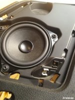
Basically I have finished the fitting of all of the speakers with the exception of the front speaker as I am waiting for a delivery (see below).
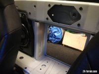
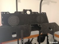
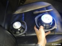
For the bulkhead, I know it you suggested to get one, but it was shockingly expensive, and when I butchered out the one I have it did have the layout of where the subwoofer cover should be, so I took the hot blade and cut them out. It was a bit of a challenge to fit the covers, since the clips did not have anything to hook on, so I warmed the plastic and pass a screw through a few clips. They are very sturdy. Will need some padding between the subs and the covers to avoid nasty rattling; but hey eventually it really looks like the one you d buy. I mean it s the same they just do not cut the circles in those cars with the basic system.
I am now working on the wires and try to understand the wiring of the basic system and how to connect it to the amplifier. I have made some wiring but waiting for the 42-pin connector to create the harness which will leave the headunit to then plug in the amp.
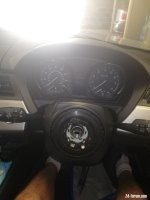
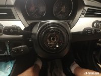
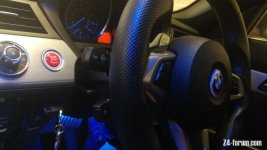
In the meanwhile I fitted the cruise control in both cars thanks to your amazing tutorial (see attached pics and video).
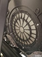
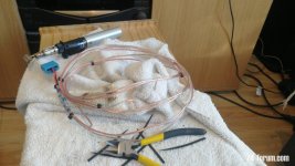
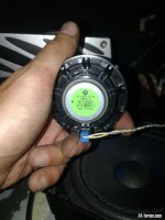
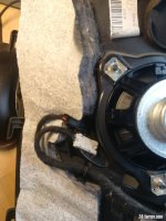
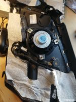
I managed to fit the subwoofer and create some custom cables, I found the connectors which were part of an adapter. So I remove one end and soldered the end I needed to a wire. Now will just need to solder to the relevant pins in the 42-pin connector when I get it (pins 3 & 4 left sub; 22 & 23 right sub).
Para 4 - new centre dash top speaker is fed from pins 39 & 40 of the 676 amplifier.
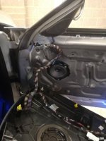
>> I decided that I am not going to butcher the front of the car dashboard and I will fit it on the bulkhead as it were the centre speaker + tweeter in the top range system. It will not make any difference, if not to give me less work, and also I like more sounds coming from the back. I bought the tweeter also which I will jump on the speaker. There is no need for the speaker support as it is interleaved between the speaker cover and the bulkhead, I just need screws to hold it, and the speaker cover embeds support for the tweeter. So no problem. See pics.
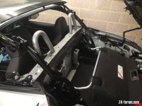
Para 6 - there are pass-through points on both the right and left sides of the bulkhead between the passenger compartment and the trunk. I'm not sure exactly where BMW route the speaker wires from the headunit, it's either one of the sills (possibly passenger side) or the central tunnel under the centre console.
Since I am waiting for the 42-pin connector, meanwhile I am making the wires AMP>> speakers. Though I need to butcher the car further, my partner has the 676 system already and from what I could see it looks like that the major harness is going through the passenger side. So I think I will let these wires go through the passenger side and then through the glove box to the headunit. This is where I will cut the relevant cables which currently are going to the speakers from the head unit.
Then I will do pass the same way for those cables which need to go from the head unit to the amplifier. I am still unsure about these as I haven’t gone in depth, but I understand there should be at least 4 channels to go to the amp. One for the front speaker set and one for the rear speaker set.
There are a few things I am also not sure of yet.
New points:
1. The way I connect the power supply from the junction box (i.e., fuse box). Am I supposed to find an empty 20 amperes slot in the fuse box? And if so, what is the kind of connector I would require?
2. What and where is the aerial diversity module? Is one of those in the boot? Currently pin 13 from head unit (black wire) goes to it, but then I see that pin 10 amp will have to connect to pin 1 of this module and still to pin 13 of head unit. Do I make a Y section? So I have one wire coming out of the amp which then splits into 2 wire, one going to aerial and one going to the head unit (CIC)? Sorry I am not good at reading diagrams.
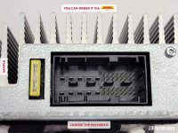
3. This brings me to this last point. In the diagram I find this type of wiring below. What does it mean? Is this like a Y section where one wire splits in 2 branches. So I see in the shot below that in the basic system pin 3 and 7 supply both subwoofer front left and front mid range speaker? And the same applies in the s676 where pin 41 and 42 supply to both front subwoofers? So the cable splits in two?


4. The pin 26 in the amplifier is the ground from what I understand. Where do I connecting to, just the car frame somewhere suitable?
5. I have had some concerns for when I have you cross-compared the diagram you sent of the basic system to the one of the amplifier. I have created a coding system in excel (see attached) since I need to match up the colours. The concerns are the following:
a. We have two e89 35i, one with the s676. In this one the wire colours between the headunit and the amplifier match up (see attached file); however they do not match up with the diagram you sent and I do not get why.
b. I realised that the diagram of the s676 you sent is not showing this active sound design module. So I tried to look on the newtis to see if I could find something. I found this
https://www.newtis.info/tisv2/a/en/...sound-output/hifi-loudspeaker-system/HTO8Ksfp
This wiring colours though do not match those I found in the car with the s676 sound system.
Regardless of the colour coding though, though the pin numbers seem consistent.
Do you know where this active sound design (ASD) is? Is it the one just underneath the headunit? Any idea as to how to take it out real quick?
My understanding here is that the ASD relays this wiring to the amplifier. So I can assume that in the e89 with the s676 we have, the wiring colour system is the same through headunit >> ASD >> amplifier.
See this
https://www.newtis.info/tisv2/a/en/...sound-output/hifi-loudspeaker-system/GaRdAReW
Once I have the above sorted I will start to look into the coding by watching the last bit of your retrofit video about the CIC. I already watched it for removing the glove box etc.
Many thanks
I hope you find this interesting hopefully it might help someone out there even for other mods
Max
all of the attachments can be found here: https://1drv.ms/f/s!Amej_oQfqLHzmvhbysrEyh4qmxSyTA?e=3YMR2o
sorry it would not let me upload them all


.jpg")


 but it obviously is!