Project 2006 Z4 - restoration (Enjoy!)

Got a squeaky wiper linkage!! A really irritating 1 squeak per wipe.
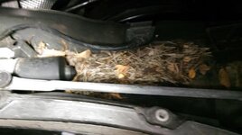
So lets have a look under the scuttle.
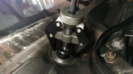
Wiper arms stuck solid so had to use my wiper removal tool
6vcDD1O.jpg

Really stuck well, so had to tap the arm with a punch and hammer to get it to free off (like breaking a ball joint by hitting the side), but a LOT more carefully. One tap and they popped off.

First view inside
Z6AbeWF.png

LSjjP2Q.jpg

6hfEiTp.png

here's the squeaky ball joint
EzCLbqK.png

Not much play in it, so squirted it with extreme synthetic lubricant.

All put back together after vacuuming out all the leaves and things!

New wiper blades completed it.

Andy.
 
I have the exact same squeak, drives me insane! I thought it was the wiper arms, so I coated them with grease, but to no avail. I shall have another look at that ballpoint tomorrow, cheers!
 
You can actually see the offending joint without removing the scuttle (if its the same one that squeaking!). I could have sprayed lube on it without dismantling.
Have a look from the drivers side down by the end of the scuttle panel.
There are 2 other ball joints also, but they were fine on mine.
Good luck.
Andy.
 
2 simple little jobs today...

here's one of only 2 exhaust heat shield bolts that I haven't removed and treated. Poor photo though, sorry.

2PMmyGM.png

The white corrosion is clearly visible due to the different metals touching each other.

So, bolt removed and white corrossion brushed away, and area above and underneath sprayed with aluminium anti-seize

MqMxSOZ.png

8WUaJEf.png

Then a stainless washer added but not before being sprayed liberally

1FtdTOo.png

And onto job number 2.....
 
Yeah, yeah, I know. What happened to the foglights?...Job in progress. When I can get round to it after fixing customers cars.

CDV, or clutch delay valve removal.

Really simple, here's a photo of before and after removal.

6DzntCE.png

98PlOD5.png

Then hydraulic circuit vacuum bled because no one else is around.

Not test driven it yet due to the weather, so it goes into the back of my workshop waiting.

PmsYVfF.png

In the foreground is my 5.7 litre camaro on the lift undergoing fuel injection conversion. A bad boy indeed !! :wink:

Andy.
 
Nows the time for roof motor relocation.
It was obvious from the start that this car wasn't on its first rodeo!!
Clips missing, etc
Anyway, I managed to get the top off the motor housing
lpS9cZf.png

Dry as a bone.
Pulled the motor out onto the plastic shelf.
7kxU0x3.png

And thats where it stopped! No matter how many tie wraps I cut and how many clips I pulled the hydraulic lines out from, it wasn't going any further. The lines were well secured down the front of the housing. It looked like the bowden cable was complicating things. So,.........a bit of thinking........I didn't want to cut the cable for reasons to be seen later.....so no option......lets remove the softop complete.

Couple of hours later and he we are
VECsvrs.png
LUArdgt.png
CfUohLS.png
4Cxrey5.png

Thought about making it into a roadster permanently, but......NO.!!

here's the lower motor housing
lg004aB.png
Dry as the proverbial desert. and the motor doesn't look 11 years old
03FAsKn.png

The line connections going in to the motor look corroded slightly, but the motor doesn't. So in my humble opinion, this has been out before and a new motor attached to the old hydraulic connections that were undoubtedly submerged in the past.
 
Here's a couple of photos of the bottom of the place where the motor housing sat
ovccSRw.png

1yMSxWr.png

and the drivers side
Fsiejtj.png

Just goes to show that keeping drain holes clear is not always the answer.

Anyway, softop replaced and motor finally pulled through. Plastic panel marked for cutting and cut out.
yTrGeW0.png

Section of rubber hose cut
gic5Cf5.png
and sharp edges sleeved for full protection to hydraulic lines and wires
6EGpj8v.png

Motor put into its place and the shelf plastic trim cut and sleeved. Unfortunately I forgot to photograph it so I put my phone through into the area where the motor used to be and took a photo there
VvERKch.png
Hopefully you can see that there is no way there will be any chafing!

And now the bowden cable.
I need a factory look, so I rerouted the cable back to where it waqs originally, with the exception that it now sticks through further......to here
MnarVAy.png
and secured
D3t2vAa.png

Just got to make a cover for the motor now and the car will look and act as per the handbook says. For the sanity of future owners who will actually be able to find the bowden cable red handle!

Andy.
 
Nice work again Andy I do admire your attention to detail and your positive nothing is a problem approach.
Keep the updates coming :thumbsup:
 
I've not updated everybody on the foglights. So, here goes
After media blasting and lens cleanup
5Vy3Pdl.png

That's the condensation ventilation hole

W0pUnEx.png
6yTtVLn.png
DquGY7Q.png

I haven't polished the lens up yet though.

Got absolutly no idea what I am going to do to the housings yet. May do simple silver paint, or alloy polish and lacquer or insert polished stainless steel plates, or even turn to DRL's.
Andy.
 
Great minds Andy, I took my fogs out with this intention but have been having a right mare trying to split them. Got any tips? I can't blast them clean but end goal is to put DRLs behind the lens, maybe paint reflector matt black.
 
Aluminium is a pig to keep shiny, looks good polished up but tarnishes quickly and lacquer rarely bonds well. The DRL option looks the best solution :thumbsup:
 
Scooba_Steve said:
Great minds Andy, I took my fogs out with this intention but have been having a right mare trying to split them. Got any tips? I can't blast them clean but end goal is to put DRLs behind the lens, maybe paint reflector matt black.

I clamped them in a vice best i could and used a hot air gun (hair drier wont work) on the aluminium to heat it up as much as I could. I then kept levering between the lens and the alloy housing with a big flat blade screwdriver .
Took about 30 mins continual heating and levering till I could get them clear.
Secret is to get the alloy hot to soften the sealant.

I like the DRL's idea and the black paint, but would rather keep them as stock as possible. makes a change for me!! Most cars I build end up as full custom!

Andy.
 
I like the idea of tucking some DRL's inside the foglight housings, although if I ever finish the angel eyes project I'm working on I guess I won't need them as well. I am curious if anyone has a tip on what to wire the DRL's to so that they turn off when the dip/main lights go on (it's illegal here to have DRL's on at the same time as the main or dipped headlights)
 
enzed4 said:
I like the idea of tucking some DRL's inside the foglight housings, although if I ever finish the angel eyes project I'm working on I guess I won't need them as well. I am curious if anyone has a tip on what to wire the DRL's to so that they turn off when the dip/main lights go on (it's illegal here to have DRL's on at the same time as the main or dipped headlights)

Here's a really quick sketch of a possible solution using a 5 pin relay spliced into dip beam circuit. This will only work if dip stays on with main beam. Not sure on z4 until I check mine (and its buried in the back of my workshop!!)

93NnMJG.png

Notice pin 87a is the one that is normally closed (NC). i.e. connected to pin 30 when not energised.

Andy.

PS Can also be done via logic gates (ic's).
 
andyfanshawe said:
enzed4 said:
I like the idea of tucking some DRL's inside the foglight housings, although if I ever finish the angel eyes project I'm working on I guess I won't need them as well. I am curious if anyone has a tip on what to wire the DRL's to so that they turn off when the dip/main lights go on (it's illegal here to have DRL's on at the same time as the main or dipped headlights)

Here's a really quick sketch of a possible solution using a 5 pin relay spliced into dip beam circuit. This will only work if dip stays on with main beam. Not sure on z4 until I check mine (and its buried in the back of my workshop!!)

IMAG0966_zpsvsaqqnmt.jpg~original


Notice pin 87a is the one that is normally closed (NC). i.e. connected to pin 30 when not energised.

Andy.

PS Can also be done via logic gates (ic's).

or just purchase the kit - link here
 
Back
Top Bottom