** UPDATE ** - 14th December 2019
I am now "out of stock" and won't be fabricating anymore (To be cost effective I have to order in bulk of 30 so not worth me getting anymore unless there was a sudden influx of interest again) -- Thanks to everyone for their over whelming interest in this project - it certainly took off more than I ever imagined! I was originally just showing off my own project ha
------------------------------------------------------------------------------------------------------------------------
Whew, the time has finally come where I can do a proper write up. Please bear with my ramblings in this post, I will try to keep it as relevant and informative as possible.")
I've had so many messages about this project on Facebook with dozens wanting to buy one off me or wanting to pay me to make one... However, from my years of experience in dealing with projects like this (not car related) people never want to pay for the time, skill & labour that goes into the finished product. I have to stress, I am just 1 person, doing this as a hobbyist. I don't get any reduced prices, I certainly can't afford to order wholesale quantities and I'll never be able to "compete" with £25 off the shelf mass produced products.
So please, I recommend looking around eBay and AliExpress, getting the cheapest bits you can from the list and having a go yourself - because if I do it all for you - it WILL be expensive! - probably around £150 inc postage, plus you'd be waiting about 2 months (4-6 weeks of that is the delivery time from China for the parts) So again, DIY is the much better route.
Bill Of Materials: (Prices at time of writing this post)
Clear 3rd Brake Light: £23 - £30 (depending on where you source it from.)
AliExpress: https://www.aliexpress.com/item/32904717645.html
eBay: https://www.ebay.co.uk/itm/401781230484
Controller
Controller PCB: £3 +postage (I've need to goto post office to get price of postage but I would guess about £1.50)
Available from myself. This will come pre-soldered with the 12 SMD resistors and the 1000uf capacitor.
(See pics below in the guide)
1 x 1N4148 Diode (on the main +12v input) -- this is included with the PCB
1 x Slide Switch (To turn on or off the indicator function - this is so you don't have to worry about editing code to be able to do it) -- this is included with the PCB
Arduino Nano: £2.12
AliExpress: https://www.aliexpress.com/item/32347096044.html
MP1584EN: £0.38 + £1.03 shipping
AliExpress: https://www.aliexpress.com/item/32950225230.html
(5v Output variant. The variable version is also fine, but be sure to use a multimeter and set to 5v BEFORE soldering in place)
3D Printed Housing: £5 - If you have a 3D Printer yourself, the STL files are attached at the bottom of the guide along with all other files for the project
Brake Light LEDs & PCB
There's 2 methods to choose from for the brake light. It depends on your preferred method.
The first method I documented here:
METHOD 1
20 x WS2812B LEDs: £9.50 (Each LED is pre soldered onto a circular PCB complete with required capacitors & resistors etc)
Amazon: https://www.amazon.co.uk/WS2812B-board-integrated-controller-WS2811/dp/B01BVDRI2W
METHOD 2
Custom PCB same shape as the PCB that is removed in order to fit this. £3 + postage from myself. (See pics below in the guide)
1 x 470ohm 1206 Resistor -- This is included and pre-soldered to the PCB.
20 x WS2812B LEDs (individual LED for SMD soldering) £2.59
AliExpress: https://www.aliexpress.com/item/32810203444.html
20 x 100nF 0805 SMD Capacitors: £2.14 in a pack of 50
eBay: https://www.ebay.co.uk/itm/300745238513
OR 20 x 100nF 1206 SMD Capacitors: £2.19 in a pack of 25 (Bear in mind these will tricker to line up with the pads as they are larger than 0805)
eBay: https://www.ebay.co.uk/itm/122455255486
CURRENT PCB STOCK
Controller Board PCB: 30 -> 3 remaining
Brake Light PCB: 20 -> 0 Remaining -- ALL GONE
The Build
I already documented my METHOD 1 approach here: https://z4-forum.com/forum/viewtopic.php?f=2&t=116841 so please take a look at that topic to see how put it all together. The rest of this guide will follow my newer METHOD 2 with my custom PCB.
Starting with the controller:
Top of the PCB (left) | Bottom of the PCB (right)

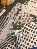
Completed Board:

As mentioned, the SMD Resistors will come pre-soldered by myself and also the Capacitor seen in the pics. Leaving just the Arduino Nano and the MP1548EN to be soldered on as well as a switch to enable / disable the indicators and also the jumper for indicator type selection (no connection = animated sequential, jumper connected = static flash (no animation))
It is up the the individual on how you choose to attach the wires - you can use screw terminal headers with a 2.54mm pitch (as pictured above) OR you can solder each of them directly into the board (pictured below [note: not all wires were attached at time of pic])

The connections are as follows:
+ = +12v from vehicle - please attach a 1N4148 Diode inline. 1 is included with the PCB so you don't need to source this yourself.
- = GND from vehicle
B = +ve feed from BRAKE
R = +ve feed from REVERSE
L = +ve feed from LEFT indicator
R = +ve feed from RIGHT indicator
1 = +12v CUSTOM INPUT 1. Eg, run a +12v wire from ignition or battery to a switch, then from the switch to this input.
2 = +12v CUSTOM INPUT 2. Eg, run a +12v wire from ignition or battery to a switch, then from the switch to this input.
The Arduino Code:
You will need to download the Arduino IDE from here: https://www.arduino.cc/en/Main/Software
You will also need to install the Adafruit NeoPixel Library - you can read how to do that here:
https://learn.adafruit.com/adafruit-neopixel-uberguide/arduino-library-installation
The short version to installing the library though is to do this "From the Sketch menu, > Include Library > Manage Libraries... In the text input box type in "NeoPixel". Look for "Adafruit NeoPixel by Adafruit" and select the latest version by clicking on the popup menu next to the Install button. Then click on the Install button. After it's installed, you can click the "close" button."
My Arduino code for this project is included at the bottom of this post in the "Files" part of the write up.
You can read a how-to here: https://www.arduino.cc/en/main/howto regarding connecting the the Arduino and uploading the sketch.
You may require alternative "CH340" drivers especially if you have a clone Arduino (Which all the cheap ones are). I have attached drivers for both Windows and Mac OSX also in the files part at the bottom.
If you've used an Arduino before please do take a look at the code, offer me some feedback or some tweaking to improve it.
*YOU DO NOT NEED TO KNOW ANY PROGRAMMING LANGUAGE TO USE MY CODE AS-IS. SIMPLY CONNECT YOUR ARDUINO, OPEN UP MY 'SKETCH' AND THEN UPLOAD IT TO THE ARDUINO NANO*
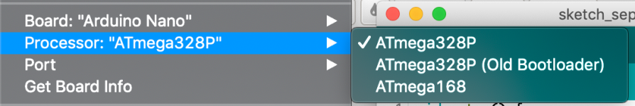
If you're having troubles uploading the sketch, a) Make sure your board type is set to Arduino Nano, and in some cases you may need to select the "(Old Bootloader)" variant as pictured below -- the second option

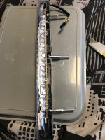
Clear 3rd Brake Light
The underside of the light is merely clipped into place. It is, however glued to the lens on the top front edge and also along the edge of each side.


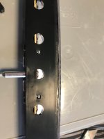
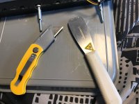
Take your time, and gently use a stanley blade or a spatula type tool to crack it open. I found myself switching between these two:

Gently cracking the glue on the sides first, before then scoring and GENTLY prizing it apart across the top

Once cracked open successfully, it should look like this:

The PCB will simply unclip from its place very easily. When I designed my PCB I had traced the OEM PCB and after designing it in Fritzing I had JLCPCB create a batch of PCBs for me. Their "accuracy" is something like 0.5% - 1% in terms of dimensions so you may need to do a little filing to my PCB notches although mine fitted nice and snug and I only needed to file a teeny tiny part to make it clip in place.
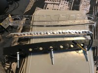
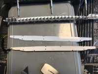
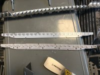
Here's a comparison of the PCB that comes in the light, compared to mine.


Next comes the not-so-fun part! Soldering on the 20 capacitors and the 20 LEDs! (The 470ohm resistor seen in the pic comes pre-soldered)

This is a picture of the individual LED:

Here are some soldered in place with the caps too:

IMPORTANT: The LEDs MUST be soldered in place in the correct orientation. Each LED has a "Step" or a "Notch" in one corner. This notch marks the GND (Pin 3) of the LED. This MUST be pointing towards the BOTTOM of the PCB as pictured below


Here's the PCB Completed:

I have circled in black the corner with notch on of each LED (The GND pin). The connections to add your wires to are on the RIGHT hand side - the same edge as the resistor - so you need to connect 3 wired to the +5v DI GND pins (Circled in RED in the picture below)

Once again (As per my previous method) you will need a conical drill bit to enlarge the LED holes since the WS2812 LEDs are larger than the OEM ones.

This time I drilled my holes out to 11/32 on the conical drill.

Plug it into the Arduino and make sure it all works:
[youtube]nWtZOUP68Nc[/youtube]
Next you want to put the PCB in place:

Then seal the light back up. I did this in a 2 step process to allow glue to dry etc.
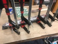
First step I did was to use super glue on the under side, across the edge/lip and then use clamps to keep the edges pressed down whilst it dried.

Once dried, I used silicone across the top and used my finger to run along the edge and kinda get it into the teeny tiny gaps from cracking it open. I then left it to sit for 24 hours to cure. DO NOT USE SUPERGLUE - It will most likely end up running across the inside of the lens - I made that mistake first time around! ha This is my second brake light due to that little balls-up
Finally comes the 3D Printed case for the controller
This was my final design:

PCB In place in the housing:
INPUT Wires

USB Connection:

USB Connection Cover (Tight push fit into the USB hole):

LED Connection:

FILES:
3D Printed Housing STIL Files: http://files.iamorion.co.uk/drive/s/taA8TiZvtnobpWDsUCmUNVlTSfgofM
Arduino Code (OLD): http://files.iamorion.co.uk/drive/s/wPyvJ3S8cKFmdqXw5WWau8Lw0EdcCj
Arduino Code (LATEST v1.4): http://files.iamorion.co.uk/drive/s/lhYBIdx8vd0CEskw0xya3WBUXol284
Controller Component List: http://files.iamorion.co.uk/drive/s/nVtn3K35BdgI1TPdIiy8Lhs1Dfq8eA (Download the html file)
CH340 Driver for Mac OSX: http://files.iamorion.co.uk/drive/s/tY4lBftuQcgyf0wfKylAJKef38fwny
CH340 Driver for Windows: http://files.iamorion.co.uk/drive/s/HPWCUb386eZoDNqZjXxxFGUvqsNKj4
CH340 Drivers Source: https://sparks.gogo.co.nz/ch340.html
Fritzing Diagram:

That was a very long post - so congrats if you made it through!
Please let me know if I've missed something out or you have any questions so I can answer them and update this post as required.
I am now "out of stock" and won't be fabricating anymore (To be cost effective I have to order in bulk of 30 so not worth me getting anymore unless there was a sudden influx of interest again) -- Thanks to everyone for their over whelming interest in this project - it certainly took off more than I ever imagined! I was originally just showing off my own project ha
------------------------------------------------------------------------------------------------------------------------
Whew, the time has finally come where I can do a proper write up. Please bear with my ramblings in this post, I will try to keep it as relevant and informative as possible.
I've had so many messages about this project on Facebook with dozens wanting to buy one off me or wanting to pay me to make one... However, from my years of experience in dealing with projects like this (not car related) people never want to pay for the time, skill & labour that goes into the finished product. I have to stress, I am just 1 person, doing this as a hobbyist. I don't get any reduced prices, I certainly can't afford to order wholesale quantities and I'll never be able to "compete" with £25 off the shelf mass produced products.
So please, I recommend looking around eBay and AliExpress, getting the cheapest bits you can from the list and having a go yourself - because if I do it all for you - it WILL be expensive! - probably around £150 inc postage, plus you'd be waiting about 2 months (4-6 weeks of that is the delivery time from China for the parts) So again, DIY is the much better route.
Bill Of Materials: (Prices at time of writing this post)
Clear 3rd Brake Light: £23 - £30 (depending on where you source it from.)
AliExpress: https://www.aliexpress.com/item/32904717645.html
eBay: https://www.ebay.co.uk/itm/401781230484
Controller
Controller PCB: £3 +postage (I've need to goto post office to get price of postage but I would guess about £1.50)
Available from myself. This will come pre-soldered with the 12 SMD resistors and the 1000uf capacitor.
(See pics below in the guide)
1 x 1N4148 Diode (on the main +12v input) -- this is included with the PCB
1 x Slide Switch (To turn on or off the indicator function - this is so you don't have to worry about editing code to be able to do it) -- this is included with the PCB
Arduino Nano: £2.12
AliExpress: https://www.aliexpress.com/item/32347096044.html
MP1584EN: £0.38 + £1.03 shipping
AliExpress: https://www.aliexpress.com/item/32950225230.html
(5v Output variant. The variable version is also fine, but be sure to use a multimeter and set to 5v BEFORE soldering in place)
3D Printed Housing: £5 - If you have a 3D Printer yourself, the STL files are attached at the bottom of the guide along with all other files for the project
Brake Light LEDs & PCB
There's 2 methods to choose from for the brake light. It depends on your preferred method.
The first method I documented here:
METHOD 1
20 x WS2812B LEDs: £9.50 (Each LED is pre soldered onto a circular PCB complete with required capacitors & resistors etc)
Amazon: https://www.amazon.co.uk/WS2812B-board-integrated-controller-WS2811/dp/B01BVDRI2W
METHOD 2
Custom PCB same shape as the PCB that is removed in order to fit this. £3 + postage from myself. (See pics below in the guide)
1 x 470ohm 1206 Resistor -- This is included and pre-soldered to the PCB.
20 x WS2812B LEDs (individual LED for SMD soldering) £2.59
AliExpress: https://www.aliexpress.com/item/32810203444.html
20 x 100nF 0805 SMD Capacitors: £2.14 in a pack of 50
eBay: https://www.ebay.co.uk/itm/300745238513
OR 20 x 100nF 1206 SMD Capacitors: £2.19 in a pack of 25 (Bear in mind these will tricker to line up with the pads as they are larger than 0805)
eBay: https://www.ebay.co.uk/itm/122455255486
CURRENT PCB STOCK
Controller Board PCB: 30 -> 3 remaining
Brake Light PCB: 20 -> 0 Remaining -- ALL GONE
The Build
I already documented my METHOD 1 approach here: https://z4-forum.com/forum/viewtopic.php?f=2&t=116841 so please take a look at that topic to see how put it all together. The rest of this guide will follow my newer METHOD 2 with my custom PCB.
Starting with the controller:
Top of the PCB (left) | Bottom of the PCB (right)
Completed Board:
As mentioned, the SMD Resistors will come pre-soldered by myself and also the Capacitor seen in the pics. Leaving just the Arduino Nano and the MP1548EN to be soldered on as well as a switch to enable / disable the indicators and also the jumper for indicator type selection (no connection = animated sequential, jumper connected = static flash (no animation))
It is up the the individual on how you choose to attach the wires - you can use screw terminal headers with a 2.54mm pitch (as pictured above) OR you can solder each of them directly into the board (pictured below [note: not all wires were attached at time of pic])
The connections are as follows:
+ = +12v from vehicle - please attach a 1N4148 Diode inline. 1 is included with the PCB so you don't need to source this yourself.
- = GND from vehicle
B = +ve feed from BRAKE
R = +ve feed from REVERSE
L = +ve feed from LEFT indicator
R = +ve feed from RIGHT indicator
1 = +12v CUSTOM INPUT 1. Eg, run a +12v wire from ignition or battery to a switch, then from the switch to this input.
2 = +12v CUSTOM INPUT 2. Eg, run a +12v wire from ignition or battery to a switch, then from the switch to this input.
The Arduino Code:
You will need to download the Arduino IDE from here: https://www.arduino.cc/en/Main/Software
You will also need to install the Adafruit NeoPixel Library - you can read how to do that here:
https://learn.adafruit.com/adafruit-neopixel-uberguide/arduino-library-installation
The short version to installing the library though is to do this "From the Sketch menu, > Include Library > Manage Libraries... In the text input box type in "NeoPixel". Look for "Adafruit NeoPixel by Adafruit" and select the latest version by clicking on the popup menu next to the Install button. Then click on the Install button. After it's installed, you can click the "close" button."
My Arduino code for this project is included at the bottom of this post in the "Files" part of the write up.
You can read a how-to here: https://www.arduino.cc/en/main/howto regarding connecting the the Arduino and uploading the sketch.
You may require alternative "CH340" drivers especially if you have a clone Arduino (Which all the cheap ones are). I have attached drivers for both Windows and Mac OSX also in the files part at the bottom.
If you've used an Arduino before please do take a look at the code, offer me some feedback or some tweaking to improve it.
*YOU DO NOT NEED TO KNOW ANY PROGRAMMING LANGUAGE TO USE MY CODE AS-IS. SIMPLY CONNECT YOUR ARDUINO, OPEN UP MY 'SKETCH' AND THEN UPLOAD IT TO THE ARDUINO NANO*
If you're having troubles uploading the sketch, a) Make sure your board type is set to Arduino Nano, and in some cases you may need to select the "(Old Bootloader)" variant as pictured below -- the second option
Clear 3rd Brake Light
The underside of the light is merely clipped into place. It is, however glued to the lens on the top front edge and also along the edge of each side.
Take your time, and gently use a stanley blade or a spatula type tool to crack it open. I found myself switching between these two:
Gently cracking the glue on the sides first, before then scoring and GENTLY prizing it apart across the top
Once cracked open successfully, it should look like this:
The PCB will simply unclip from its place very easily. When I designed my PCB I had traced the OEM PCB and after designing it in Fritzing I had JLCPCB create a batch of PCBs for me. Their "accuracy" is something like 0.5% - 1% in terms of dimensions so you may need to do a little filing to my PCB notches although mine fitted nice and snug and I only needed to file a teeny tiny part to make it clip in place.
Here's a comparison of the PCB that comes in the light, compared to mine.
Next comes the not-so-fun part! Soldering on the 20 capacitors and the 20 LEDs! (The 470ohm resistor seen in the pic comes pre-soldered)
This is a picture of the individual LED:
Here are some soldered in place with the caps too:
IMPORTANT: The LEDs MUST be soldered in place in the correct orientation. Each LED has a "Step" or a "Notch" in one corner. This notch marks the GND (Pin 3) of the LED. This MUST be pointing towards the BOTTOM of the PCB as pictured below
Here's the PCB Completed:
I have circled in black the corner with notch on of each LED (The GND pin). The connections to add your wires to are on the RIGHT hand side - the same edge as the resistor - so you need to connect 3 wired to the +5v DI GND pins (Circled in RED in the picture below)
Once again (As per my previous method) you will need a conical drill bit to enlarge the LED holes since the WS2812 LEDs are larger than the OEM ones.
This time I drilled my holes out to 11/32 on the conical drill.
Plug it into the Arduino and make sure it all works:
[youtube]nWtZOUP68Nc[/youtube]
Next you want to put the PCB in place:
Then seal the light back up. I did this in a 2 step process to allow glue to dry etc.
First step I did was to use super glue on the under side, across the edge/lip and then use clamps to keep the edges pressed down whilst it dried.
Once dried, I used silicone across the top and used my finger to run along the edge and kinda get it into the teeny tiny gaps from cracking it open. I then left it to sit for 24 hours to cure. DO NOT USE SUPERGLUE - It will most likely end up running across the inside of the lens - I made that mistake first time around! ha This is my second brake light due to that little balls-up
Finally comes the 3D Printed case for the controller
This was my final design:
PCB In place in the housing:
INPUT Wires
USB Connection:
USB Connection Cover (Tight push fit into the USB hole):
LED Connection:
FILES:
3D Printed Housing STIL Files: http://files.iamorion.co.uk/drive/s/taA8TiZvtnobpWDsUCmUNVlTSfgofM
Arduino Code (OLD): http://files.iamorion.co.uk/drive/s/wPyvJ3S8cKFmdqXw5WWau8Lw0EdcCj
Arduino Code (LATEST v1.4): http://files.iamorion.co.uk/drive/s/lhYBIdx8vd0CEskw0xya3WBUXol284
Controller Component List: http://files.iamorion.co.uk/drive/s/nVtn3K35BdgI1TPdIiy8Lhs1Dfq8eA (Download the html file)
CH340 Driver for Mac OSX: http://files.iamorion.co.uk/drive/s/tY4lBftuQcgyf0wfKylAJKef38fwny
CH340 Driver for Windows: http://files.iamorion.co.uk/drive/s/HPWCUb386eZoDNqZjXxxFGUvqsNKj4
CH340 Drivers Source: https://sparks.gogo.co.nz/ch340.html
Fritzing Diagram:
That was a very long post - so congrats if you made it through!
Please let me know if I've missed something out or you have any questions so I can answer them and update this post as required.
Attachments
-
 arduino.png223.6 KB · Views: 3,271
 -
 IMG_0087.jpeg319 KB · Views: 3,271
 -
 IMG_0070.jpeg198.4 KB · Views: 3,271
 -
 IMG_0071.jpeg99.7 KB · Views: 3,271
 -
 IMG_0074.jpeg180.4 KB · Views: 3,271
 -
 IMG_0072.jpeg176.2 KB · Views: 3,271
 -
 IMG_0073.jpeg207.2 KB · Views: 3,271
 -
 IMG_0075.jpeg182.6 KB · Views: 3,271
 -
 IMG_0076.jpeg184.5 KB · Views: 3,271
 -
 IMG_0083.jpeg206.2 KB · Views: 3,271

")