Following on from my previous post about a custom 3rd Brake Light (https://z4-forum.com/forum/viewtopic.php?f=2&t=116841), I mentioned I was designing my own PCB controller as I'd had lots of interest in it, especially on Facebook where I received over 50+ messages within a few hours of posting in a group 

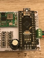
Well, all the way from China, my PCB I designed using "Fritzing" arrived. Here's some pics of the PCB and my first 'build' (Adding the components) as you can see, it's a nice size - measuring 45mm x 45mm - obviously will get a little larger once I've made the case/housing which I'll be doing later this evening and 3D Printing.
I'm now just awaiting my custom PCB to arrive to make replacing the LEDs in the brake light much easier too (I'll update again with pics when they arrive). I've designed a PCB that's the same size and shape as the piece that you remove from these chinese brake lights, so no glueing individual LEDs in and messing around joining them all together, it'll just be a case of making holes a little larger, then a straight PCB swap & then soldering on 3 wires of your preferred length to route through into the boot to where ever you choose to hide the little controller)
Anyway, without further ado, pics of the PCB 8)
Top (left) | Bottom (right)
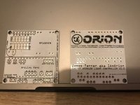
Top
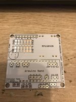
Arduino Nano & MP1584EN Soldered in place
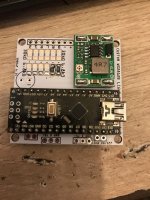
SMD Resistors on
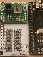
Capacitor, Jumper & Screw Terminal for light connection
Back after soldering (excuse the flux mess, I haven't cleaned it yet)
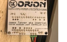
Before anyone asks, my plan is to poss to sell the PCBs to people wanting to DIY this - whilst I will leave the Arduino and MP1584EN soldering to whoever wants one, I WILL solder on the SMD resistors because I know some hobbyists struggle or just don't like dealing with SMD components. Everything else is "Through Hole (THT)" so easy peasy.
For those curious of the connections...
+ = +12v from vehicle
- = GND from vehicle
B = +ve feed from BRAKE
R = +ve feed from REVERSE
L = +ve feed from LEFT indicator
R = +ve feed from RIGHT indicator
1 = +12v CUSTOM INPUT 1. Eg, run a +12v wire from ignition or battery to a switch, then from the switch to this input.
2 = +12v CUSTOM INPUT 2. Eg, run a +12v wire from ignition or battery to a switch, then from the switch to this input.
Well, all the way from China, my PCB I designed using "Fritzing" arrived. Here's some pics of the PCB and my first 'build' (Adding the components) as you can see, it's a nice size - measuring 45mm x 45mm - obviously will get a little larger once I've made the case/housing which I'll be doing later this evening and 3D Printing.
I'm now just awaiting my custom PCB to arrive to make replacing the LEDs in the brake light much easier too (I'll update again with pics when they arrive). I've designed a PCB that's the same size and shape as the piece that you remove from these chinese brake lights, so no glueing individual LEDs in and messing around joining them all together, it'll just be a case of making holes a little larger, then a straight PCB swap & then soldering on 3 wires of your preferred length to route through into the boot to where ever you choose to hide the little controller)
Anyway, without further ado, pics of the PCB 8)
Top (left) | Bottom (right)

Top

Arduino Nano & MP1584EN Soldered in place

SMD Resistors on

Capacitor, Jumper & Screw Terminal for light connection

Back after soldering (excuse the flux mess, I haven't cleaned it yet)

Before anyone asks, my plan is to poss to sell the PCBs to people wanting to DIY this - whilst I will leave the Arduino and MP1584EN soldering to whoever wants one, I WILL solder on the SMD resistors because I know some hobbyists struggle or just don't like dealing with SMD components. Everything else is "Through Hole (THT)" so easy peasy.
For those curious of the connections...
+ = +12v from vehicle
- = GND from vehicle
B = +ve feed from BRAKE
R = +ve feed from REVERSE
L = +ve feed from LEFT indicator
R = +ve feed from RIGHT indicator
1 = +12v CUSTOM INPUT 1. Eg, run a +12v wire from ignition or battery to a switch, then from the switch to this input.
2 = +12v CUSTOM INPUT 2. Eg, run a +12v wire from ignition or battery to a switch, then from the switch to this input.