⌛Y3 & Y4 Roof Diagnostic System (for all convertible & roadster)

RobbiZ4

Senior member
The 3rd generation of my roof diagnostic system got finished in these days, after a conceptual phase of about 2 years:

Just have a look at some pictures on the German ZRoadster forum of the final build phase. 🤣


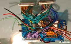
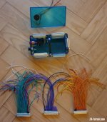
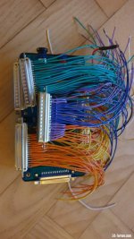
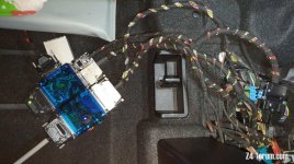
One individual Y-cable for each of the 4 CTM plugs lead all signals to an E89 specific concentrator (big blue box) in the trunk.

1st 18-pole Y-cable with 2x18=36 wires:
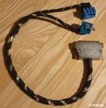
20210407_y-cable18pole.jpg

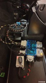
All 4 Y-cables connected to the CTM as well as to the concentrator K1 (BlueBox):
20210505_183356_sm.jpg
The attached remote control unit supports opening and closing of the roof as well as of the front locking system.


These signals are concentrated on 2 different collections of 16 analog as well as 8 digital channels in parallel.
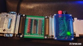
20210506_130638_sm.jpg

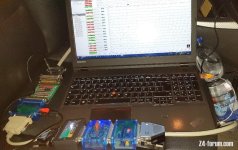
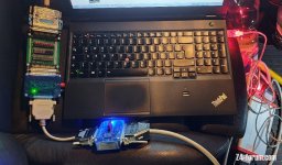
All 24 channels are transfered by an AD converter to support a specific software on my notebook (on the passengers seat of my Z4).
20210506_130606_sm.jpg

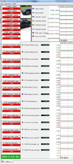
Live plot of all 24 signals while opening the roof.
BMW_E89_B6-EN_V8_sm.jpg

Advantage:
This tool works completely independant of any fault collection system.
I just have to compare each individual chart with a reference of a well working roof to identify issues on wires, components like hallsensors and microswitches as well as on the timing of the opening or closing process.
 
Last edited:
Smartbear said:
... does your data logger replay in slow mo so you can see the chain of events?
Rob
Yes it does and you can replay the sequence in a later diagnostic session.

But interestingly, that is not required:
There is a live running timeline on the screen, exactly as an EKG at the doctor's. So I've called it "roof EKG".

As the roof in general stops on the first issue, you always will see it live! The timeline continous to run on the screen and all signals keep their current level, low or high, wire broken or wires shortened!

On the following you will see a chart of the two microswitches in the rear roof shell, where the right one (blue) fails while closing due to a broken wire:
Bild1.jpg

Taking a hardcopy of the whole window to store it on the filesystem for documentation is all, I have to do
And the source issue of a completely not working roof can be seen in comparing the current view with a former taken reference chart. Really easy going.
 
The most valued advantage is, that with the help of the jumpers on the green board, I can replace an internal faulty component of the roof with an external attached, working component (microswitch, hallsensor).

file.php


I.e. if a wire to a microswitch in the roof shell is broken, I just pull the jumper of the corresponding channel and place an external microswitch (MS) on the board.

When I switch this external MS manually when required in the roof moving process, the non working roof can be driven into each required position for future repairs.
 
flybobbie said:
Hats off there, some work gone into that.
Thanks.

I'm still astonished by myself about those pictures taken from the build phase, especially this one of the concentrator: :D
Bild1.jpg
 
RobbiZ4 said:
The most valued advantage is, that with the help of the jumpers on the green board, I can replace an internal faulty component of the roof with an external attached, working component (microswitch, hallsensor).

I.e. if a wire to a microswitch in the roof shell is broken, I just pull the corresponding jumper and place an external microswitch (MS) on the board. When I switch this external MS manually when required in the roof moving process, the non working roof can be driven into each required position for future repairs.

That’s a fabulous way of proving the faults....I wonder if we could set up a UK resource by buying one of you plus a licence to use to help UK people ?

Or some other way to enable use of this fab resource?
 
Robbi, I’m just in amazement and awe with the thought process and skill that goes into devising and producing something like this.

Hats off to you :hattip: :hattip:
 
AnubisZed said:
...are you going to be making it available ££££ 👍 8)
Well, that's all handmade in Germany and can't be payed :D

Have a look at the initial steps to build V1 of this diagnostic system 3 years ago.

The build process didn't change in between, only the complexity.
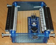
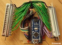
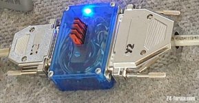
Each currently attached box contains an individual electronic board for different purposes, also developed and built by me. Even an Arduino board had to be attached to the signal lines to handle some very strange signals of the lid switches.
That's the reason, the 3rd version took all in all a bit more than 2 years to plan & build.

20210308_223006_sm.jpg

20210317_230354_sm.jpg

20210318_003903_sm.jpg

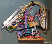
The Arduino box on the left to filter some noises from the digital lines, an inverter box on the right to invert individual digital signals if required (i.e. ground signals can be measured as well).
 
Last edited:
A funny picture of the "Inverter Box", equiped with 8 transistor based inverter groups for all 8 digital lines. All 16 analog lines are carried out 1:1.

20210105_235151_sm.jpg

With a jumper for each of the 8 channels, an inverted input signal can be sent to the analog-to-digital converter.
20210105_225450.jpg

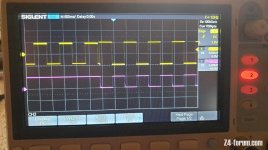
An inverted signal on the oscilloscope (IN - yellow, OUT - red):
20210226_171756_sm.jpg
 
As of today, I've completed the next concentrator box (BlueBox K2) for another couple of BMW convertibles:
  • F33 (4series)
    F83 (4series M)
    F91(M8)
    G14(8series]
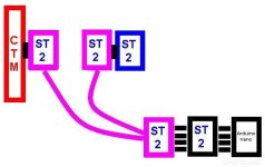
Schema of 1 Y-cable placed between the roof loom (ST2, blue) and the CTM (red).
The E89 (Z4) requires 4 different Y-cables for its 4 connectors, the F33 (4-series) requires 3 different Y-cables.
Y-Kabel_Prinzip.jpg

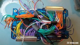
These concentrator boxes are challenging - about 220 different wires:

20210519_211651_cpr.jpg

20210519_204505_cpr.jpg

20210521_011755_cpr.jpg

20210521_224058_cpr.jpg

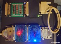
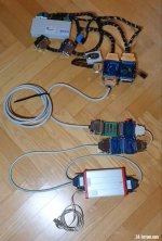
The complete diagnostic system between the CTM (on top) and the red/silver AD-converter on the bottom:
20210521_235232_cpr.jpg


The whole story in German...

and translated 4U:
 
Last edited:
[ref]RobbiZ4[/ref], I missed this initially and only just seen it.
I have absolutely no idea what you did, how it works, or how on earth you worked it all out, but.................
Brilliant! Never ceases to amaze me what people can come up with.
Up until now I had not completely understood your history behind all the roof advice you've been giving, only that you obviously knew what you were talking about.
I hope this thread enlightens people and stops any more doubting of the advice you freely and generously hand out to us.

Wunderbar! :thumbsup:
 
Thanks guys for the flowers. 👍

Well, did you have a look at the above linked details on the German website? Read the "short summary". 👍

Here directly translated by Google (not bad, but not perfect):

For the following BMW convertibles, the Y3 tool got finished (K1..5 are these blue concentrator boxes):

K1: E89 - Z4 Roadster
K1: E93 - 3-series convertible

K2: F33 - 4-series convertible
K2: F83 - M4 convertible
K2: F91 - M8 convertible
K2: G14 - 8-series convertible

K3: E46 - 3-series convertible
K3: E52 - Z8 Roadster
K3: E64 - 6-series convertible

K4: E88 - 1-series convertible
K4: F23 - 2-series convertible
K4: F12 - 6-series convertible
K4: R57 - Mini convertible
K4: R59 - Mini Roadster

K5: G29 - Z4 Roadster
K5: G29 - Boldmen CR4 https://www.boldmen.de/en/
K5: I15 - i8 Roadster
K5: F57 - Mini Cabrio

All 5 concentrator boxes (K1...K5) got completed in between, as well as tested with at a minimum of one model.
 
Last edited:
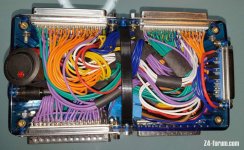
Latest test of the reworked Z4 concentrator box (K1) for our E89, that collects all 4 Y-cables connected to the roof CTM.

20210602_small1.jpg

The two 50 pole output connectors each supply 24 A/D channels in parrallel, to draw a collection of 24 timeline diagrams on a single notebook screen. The 50 pole white output cable on the left of the concentrator is connected to the following devices, placed inside the car.

Each roof activity can be seen live in these 24 diagrams: relais, pump, solenoids, locking system, microswitches, hall sensors - everything.

20210602_small2.jpg
 
Back
Top