Still problems after C/L relays replacement

Alemito

Member
 Milano, Italy
Hi everybody,
yesterday i swapped the central locking relays on the GM5 module, as i was having issues with the locks (doors not opening with key/button, drivers door lock sticking at times, errors “36” and “39” “relay short circuit/open circuit, driver/passenger side” ).

So i bought genuine Tyco relays and soldered them in, but I am now at a dead stop because this is what’s happening:

The doors will lock flawlessly, even better than before, and the drivers door lock is not sticking anymore (yay).

And that's the end of the good news as the fuel filler door and the inner cubby holes won’t lock anymore (both were working fine before the relay job). Also, the doors still won’t open no matter what, like it was before. :headbang:
I’m getting “error 41: relay unresponsive when unlocking”, but if i test the relays on the bench they’re throwing just fine. All of the board pins testing with the multimeter is ok, according to the web.

What can i do more? I’ll try slapping another set of relays in there for good measure, but any suggestion is appreciated.
If I replaced the module altogether, would it need to be coded to the VIN?
 
Wasn’t performed. But “error 41” was not there before so I *assume* the loom is good.

Has anyone got a continuity check scheme for the board relays of the Z4 module, as the e46’s GM5 layout is a tad different?
 
I would politely suggest that any new issues are likely to have been introduced by something you have done.
So reworking everything you did would be the first step.
I acknowledge that there are still existing problems that were there before, but until you have addressed the newly raised issues and returned to just the initial faults, I doubt you can move forward.
 
Quick info. Are the relays arranged like “one for locking L/R and one for unlocking L/R” or “one for left Lock/Unlock and one for right L/U”? (I know the relays are double.)
 
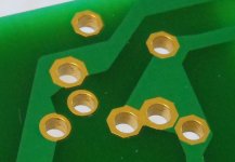
It possible that you may have damaged the through plating on the pcb holes as theses relays do not come out cleanly without some pretty high end rework gear. It's going to be hard to check without removing the relays again, but what you really need to do is check continuity between the pcb pad on the top side of the board and the corresponding pcb pad on the bottom side.

Also, since the original TYCO relays have been obsolete for a few years, it begs the question of what you have actually fitted? There are many fakes knocking around on Ebay of dubious quality (you can tell by the moulding on the base), so you have probably either fitted very old genuine relays that have been sat around in stock for years or counterfeit ones.
 
ph001 said:
It possible that you may have damaged the through plating on the pcb holes as theses relays do not come out cleanly without some pretty high end rework gear. It's going to be hard to check without removing the relays again, but what you really need to do is check continuity between the pcb pad on the top side of the board and the corresponding pcb pad on the bottom side.

Also, since the original TYCO relays have been obsolete for a few years, it begs the question of what you have actually fitted? There are many fakes knocking around on Ebay of dubious quality (you can tell by the moulding on the base), so you have probably either fitted very old genuine relays that have been sat around in stock for years or counterfeit ones.
I’m 99.9% sure I didn’t rip the tracks but I’ll check again. Can you please explain me what I have to check continuity with, in detail?
 
You know the relay trips so check the voltage on the out put leg. Then follow the track and see if its the same. If its good to the edge of the board check each side of the loom connector - assuming you can get a probe into the loom side; I don't know I never tried. If that all good then I'd try my luck at the actuator end - is the connection onto them good?
 
Alemito said:
ph001 said:
It possible that you may have damaged the through plating on the pcb holes as theses relays do not come out cleanly without some pretty high end rework gear. It's going to be hard to check without removing the relays again, but what you really need to do is check continuity between the pcb pad on the top side of the board and the corresponding pcb pad on the bottom side.

Also, since the original TYCO relays have been obsolete for a few years, it begs the question of what you have actually fitted? There are many fakes knocking around on Ebay of dubious quality (you can tell by the moulding on the base), so you have probably either fitted very old genuine relays that have been sat around in stock for years or counterfeit ones.
I’m 99.9% sure I didn’t rip the tracks but I’ll check again. Can you please explain me what I have to check continuity with, in detail?

When you have a double sided pcb, the copper tracks actually make connections THROUGH the holes. The copper in the middle of the hole is easy to tear out if you don't have a good iron / desolder tool. You need to check you have continuity through the hole from the pad on the top side to the pad on the bottom side...
Plated-through_holes_on_an_electronic_circuit_board.jpg
 
Solved!!!

Two tracks were broken. Not at the solder joints though, I realised my cutter slipped while opening the old relays to ease removal, hit the board and cut two tracks. Invisible at naked eye almost, I found it with a multimeter and a magnifying glass. Bridged and it’s like new, I’m super happy tonight :)
 
Alemito said:
Solved!!!

Two tracks were broken. Not at the solder joints though, I realised my cutter slipped while opening the old relays to ease removal, hit the board and cut two tracks. Invisible at naked eye almost, I found it with a multimeter and a magnifying glass. Bridged and it’s like new, I’m super happy tonight :)

:thumbsup: ... look for the simple stuff!
 
Anyone know a good step by step guide or video for changing these relays on the GM5 module? It's all a bit above my pay-grade so to speak, but I know a few guys who could do it with the right info to explain with!
 
Back
Top Bottom