>

Replacement of OEM Sat Nav with Garmin, retaining ‘pop-up’ functionality

Mojito

Member
My original plan was to replace the outdated OEM Sat Nav screen with an up to date phone/tablet, most importantly retaining the ‘pop-up screen’ functionality. I know aftermarket Android systems work well and offer multiple functions, but the fixed screen just doesn’t work for me. To be honest I wouldn’t use most of the apps anyway. I am just after a decent Sat Nav with OEM look, audio streaming and phone handsfree.

Replacing the OEM screen with a phone has been done before and there is an excellent, but old thread on it:

https://z4-forum.com/forum/viewtopic.php?t=56746

It features some great work by members - thank you all. However first stumbling block. The screen on an OEM Sat Nav is 16:9 format and I couldn’t find a current model phone that would fit the existing housing without modification and I wanted to retain the OEM look. I could go for an old outdated model phone, but that would gives issues with incompatibility with current apps etc. and seemed like a backwards step.

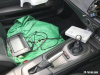
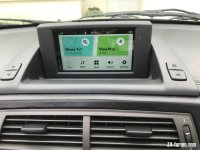
So a little brainstorming and I came up with a different solution :) It just so happens that the current model Garmin Drivesmart 66 Sat Nav screen dimensions are 16:9 and it is a perfect fit for the Sat Nav Casing screen cut out. What’s more it’s not just an excellent Sat Nav with voice control and touch screen and a bright hi-res screen, but has hands free phone functionality, music streaming from phone and there is a model with built in Alexa. Free for life map updates, wireless updating and a few other apps/features too, like live traffic updates and weather. Nearly forgot to mention there is a very neat wireless reversing camera (BC50) available for it as an extra. I don’t need it, but suspect I won’t be able to resist trying one…. just because I can :lol:

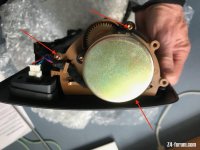
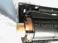
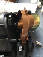
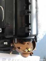
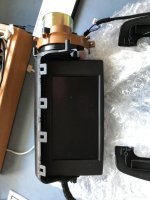
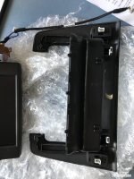
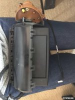
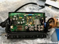
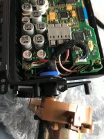
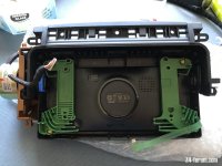
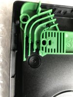
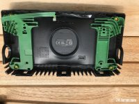
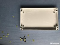
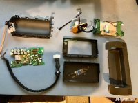
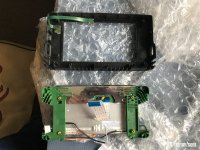
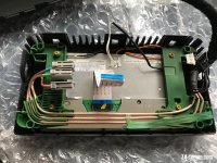
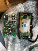
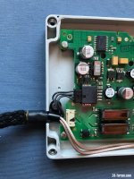
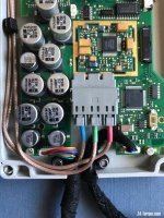
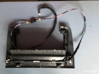
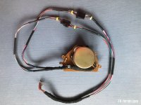
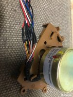
Cost for a new Garmin Drivesmart 66 with Alexa was £198 from Halfords, inc. a 10% Bank Holiday deal and free next day delivery. Secondhand ones do come up on Ebay, but predictably not on the day I decided to commit to this project. I already had a spare Sat Nav monitor as donor - fully working but with a couple of pixelated lines - ideal. There are some very minor modifications required to the pop up screen casing, which I will explain in full, but it would be entirely possible to swop the original screen back in as the monitor is not butchered :) The Garmin itself is totally unmodified :thumbsup:

A couple of potential downsides to mention:

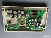
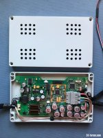
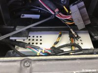
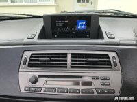
If you want to retain the radio function playing the from car headunit, you will need to change the head unit to a non sat nav one - the sat nav one doesn’t of course have a screen to display channel info. I already had one and they are readily available on Ebay for less than £60 - see photo. You can of course get round this by using Alexa to play internet radio from your phone. I tried it and it works fine, but I created havoc for my wife in the house who couldn’t understand why the house Alexa kept madly swopping stations - I was logging into same account :lol:

If you have DSP you will loose full equalisation control and just have the presets - I can live with that. You won’t be able to see car data on the Garmin Screen either, but that info is available on the car display anyway.

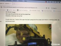
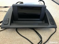
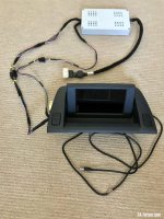
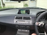
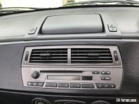
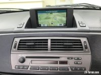
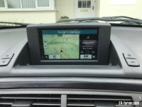
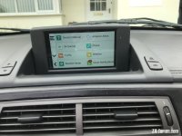
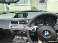
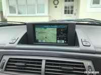
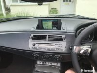
This is going to be a big thread, pic heavy, so I’ll split it into a few posts. A few photos to start showing the finished conversion. The only giveaway about from the display itself is the inscription ‘Garmin’ to the side of the screen :roll:
 

Attachments

  • IMG_6734.jpeg
    IMG_6734.jpeg
    147.7 KB · Views: 2,086
  • IMG_6735.jpeg
    IMG_6735.jpeg
    154.1 KB · Views: 2,086
  • IMG_6737.jpeg
    IMG_6737.jpeg
    120.2 KB · Views: 2,086
  • IMG_6738.jpeg
    IMG_6738.jpeg
    136.2 KB · Views: 2,086
  • IMG_6742.jpeg
    IMG_6742.jpeg
    146.4 KB · Views: 2,087
  • IMG_6743.jpeg
    IMG_6743.jpeg
    132 KB · Views: 2,087
  • IMG_6746.jpeg
    IMG_6746.jpeg
    155.9 KB · Views: 2,087
  • IMG_6748.jpeg
    IMG_6748.jpeg
    126.9 KB · Views: 2,087
  • IMG_6749.jpeg
    IMG_6749.jpeg
    132.5 KB · Views: 2,087
Swopping the Screen

I am indebted to members who shared information ten years ago on how to take a Sat Nav Monitor apart - see https://z4-forum.com/forum/viewtopic.php?t=56746

No need to repeat here, but I can help with more info and have more photos if required as sadly original photos are now missing from the thread. Important Note for anyone contemplating this. It’s not difficult, but read the entire original thread as the initial instruction misses an important step, which is mentioned later by another contributor. I’m referring to the blue plastic clip which holds one side of the screen ‘spindle/bearing’ in place. If you don’t split the screen casing and remove the clip you will never remove the screen casing from its mount. Split the screen casing from the side without clips, using a credit card. I’ve included a photo of the blue clip location.

With the screen casing split and removed from it’s mount it’s an easy, if slightly fiddly job, to disconnect the various connecting leads and remove the old screen & circuit board.

When I reached this stage I had high hopes that I could fit the Garmin without further modification and just reassemble. The screen fit is perfect and with the addition of a little double sided tape even the original green screen mounts can be used without modification.

Never that easy is it - Hurdle no 2…

The depth of the Garmin and location of it’s power/data lead meant that I couldn’t refit the circuit board which operates the stepper motor in the screen housing :headbang: I considered removing the Garmin from it’s case, but dismissed this idea as even with the right angle power/data connector I couldn’t see how I could get it all to fit. Also the Garmin alone fits really well without modification and I was reluctant to butcher it as it was brand new :) Someone else might of course try this and have a solution to fit it all in… if so it would almost be job done, just reassemble….. but I couldn’t manage it.

Anyway a little lateral thinking was required….. two obvious solutions. The first and simplest - abandon the powering for the flip up screen and simply flip it up by hand. It will be wired into a ‘live power on ignition key’ fuse and screen will turn on & off automatically. Perhaps a good solution if you have a broken Sat Nav that doesn’t flip up on power, giving your Sat Nav a new lease of life for relatively little cost/work.

I went for an alternative solution and and I’m going to let photos do most of the talking :)
Still a simple solution, but more work required :)

There is absolutely no reason why the circuit board has to be mounted in the screen housing :thumbsup: All that’s needed is to lengthen the two short cable bundles connecting the stepper motor to the circuit board. Re-route them, together with the cable which connects the monitor to the car loom and re-connect to the externally mounted circuit board which can now be mounted under the dashboard.
See photos, which will hopefully make it totally clear. It’s not difficult just 34 solder joints :)

More to follow:
 

Attachments

  • IMG_6281.jpeg
    IMG_6281.jpeg
    115.4 KB · Views: 2,084
  • IMG_6304.jpeg
    IMG_6304.jpeg
    124.4 KB · Views: 2,084
  • IMG_6308.jpeg
    IMG_6308.jpeg
    121.2 KB · Views: 2,084
  • IMG_6310.jpeg
    IMG_6310.jpeg
    115 KB · Views: 2,084
  • IMG_6312.jpeg
    IMG_6312.jpeg
    98 KB · Views: 2,084
  • IMG_6316.jpeg
    IMG_6316.jpeg
    127.5 KB · Views: 2,084
  • IMG_6317.jpeg
    IMG_6317.jpeg
    158.5 KB · Views: 2,084
  • IMG_6327.jpeg
    IMG_6327.jpeg
    169 KB · Views: 2,084
  • IMG_6328.jpeg
    IMG_6328.jpeg
    201.1 KB · Views: 2,084
  • IMG_6333.jpeg
    IMG_6333.jpeg
    153.5 KB · Views: 2,084
Time to raid the parts box.

I already had these parts from another project, but they are readily available and plenty of alternatives out there.

3 x 6 pin connectors with wires - there are 17 wires to lengthen.

I used : 2.5mm SM Male Female Connector Cable, 6 pin

https://www.ebay.co.uk/itm/182307853806

1 x Circuit Board Project casing - cut down in thickness to fit behind the panel under air con controls, where aux socket normal mounted.

I used : Electrical Enclosure Box 200 x 120 x 56mm/7.87×4.72×2.16in, ABS Box, Electrical Project Box

https://www.amazon.co.uk/dp/B08CRLH4G4?psc=1&ref=ppx_pop_dt_b_product_details


I’m hopeful the photos explain better than I can the cable lengthening process:

Firstly the two sets of cables from the stepper motor need to be unthreaded through the centre of the screen housing spindle. Then it’s just cut and splice in the leads. I love soldering and sat out in the garden on a sunny day, happily soldering and drinking coffee :lol: The reason for the connectors is for ease of threading cables when mounting in the Z. I heat shrank each wire and wrapped in automotive tape to finish.

The circuit board project case I used was perfect in two dimensions, but I cut it down in thickness so it would slip it into an easily accessible mounting position under the air con controls - see photo. For reference the thickness of my cut down box is 32mm, but not critical.

I secured all external cables, so nothing could pull out and added cooling holes, but don’t think that’s really necessary. Then it was just a case of re-assembling the monitor casing. Simply the reverse of disassembly, not forgetting to clean and lubricate the screen ‘spindle/bearings’ while it is all apart. The Garmin USB cable also needs to be threaded through the side of the Screen casing (see mod below)

A few minor mods to the casing at this point:

I drilled a paperclip diameter sized hole above the Garmin on/off switch just in case I ever needed to reboot it. It’s a very small hole and you barely notice it. I also cut back a couple of small ‘prongs’ on one of the green screen mounts as it was partially covering the button - see photo.

I drilled two 3mm holes directly above the two Garmin microphones. When the screen is closed they are totally covered by the housing and you can’t see them, they are only visible when the screen is open and I think look absolutely fine. The microphones work perfectly for Garmin/Alexa voice instructions and hands free phone, and I suspect smaller holes would actually work.

I didn’t do it, but it’s probably also worth drilling another paper clip diameter hole above the microphone on/off switch, which is located directly between the microphones.

In order to fit the USB cable through the screen ‘spindle’ a small piece of plastic needs to be removed from it - the USB plug is just slightly too big. The ‘spindle’ has a spring clip in it and I found it easiest to remove this first, slip it over the USB plug, push plug through the plastic ‘spindle’ and reassemble - see three photos, showing clip and where plastic removed.


More to follow in next post
 

Attachments

  • IMG_6668.jpeg
    IMG_6668.jpeg
    142.4 KB · Views: 2,081
  • IMG_6663.jpeg
    IMG_6663.jpeg
    123.4 KB · Views: 2,081
  • IMG_6657.jpeg
    IMG_6657.jpeg
    185.8 KB · Views: 2,081
  • IMG_6460.jpeg
    IMG_6460.jpeg
    226.3 KB · Views: 2,081
  • IMG_6458.jpeg
    IMG_6458.jpeg
    188.6 KB · Views: 2,081
  • IMG_6453.jpeg
    IMG_6453.jpeg
    212.6 KB · Views: 2,081
  • IMG_6384.jpeg
    IMG_6384.jpeg
    153.9 KB · Views: 2,081
  • IMG_6383.jpeg
    IMG_6383.jpeg
    188.3 KB · Views: 2,081
  • IMG_6372.jpeg
    IMG_6372.jpeg
    196.1 KB · Views: 2,081
  • IMG_6369.jpeg
    IMG_6369.jpeg
    236.6 KB · Views: 2,081
More Photos :)
 

Attachments

  • IMG_6697.jpeg
    IMG_6697.jpeg
    144.5 KB · Views: 2,076
  • IMG_6692.jpeg
    IMG_6692.jpeg
    211.1 KB · Views: 2,076
  • IMG_6691.jpeg
    IMG_6691.jpeg
    222.5 KB · Views: 2,076
  • IMG_6689.jpeg
    IMG_6689.jpeg
    199.3 KB · Views: 2,076
  • IMG_6686.jpeg
    IMG_6686.jpeg
    186.8 KB · Views: 2,076
  • IMG_6684.jpeg
    IMG_6684.jpeg
    191.9 KB · Views: 2,076
  • IMG_6683.jpeg
    IMG_6683.jpeg
    244.2 KB · Views: 2,076
  • IMG_6679.jpeg
    IMG_6679.jpeg
    150.1 KB · Views: 2,076
  • IMG_6677.jpeg
    IMG_6677.jpeg
    223.2 KB · Views: 2,076
  • IMG_6676.jpeg
    IMG_6676.jpeg
    78.3 KB · Views: 2,076
Have to say when I plugged the circuit board into the car loom and turned the ignition on I was somewhat relieved when the monitor opened, the switches worked and it closed on ignition off. Phew, time for a beer :D

Having got this far, it’s now a pretty easy job to remove the access panel under air con controls (credit card along top edge and prise off ) and mount the circuit board there with a sticky pad. Feed the cables in, reinstall the screen and head unit and connect the Garmin to a switched power supply - piggy back fuse off fusebox. For testing the system I hardwired the Garmin through the Aux socket, but will change this to connect through car bluetooth for best sound quality and full steering wheel button control of music function - just waiting for Bluetooth to arrive.

Setting up the Garmin is simple and the manual is excellent:

https://www8.garmin.com/manuals/webhelp/GUID-6E5DFD2E-EEE4-4EF3-89BC-AACD1B4936C7/EN-GB/GUID-7CA9147D-3677-4F4E-992C-A97B9E361C1F-homepage.html

Have to say, I’m really pleased with the finished project. The functionality of the Garmin as a sat nav alone is brilliant - screen is super bright and it just works. Even the Garmin voice control is quite good - well it works with car sat on drive, I’m a bit doubtful of how well it will work top down at speed 8) Hands free is also good and the audio app works well with track info clearly showing. I doubt I will use Alexa, but it’s there and I’ll have a play with it. I haven’t yet found a way of turning off the Garmin warning banners when it switches on, but it’s only a very minor thing.

Best of all for me I’ve given the pop up sat nav a new lease of life and it looks OEM.

More than happy to help with further info for anyone considering this :thumbsup:
 

Attachments

  • IMG_6749.jpeg
    IMG_6749.jpeg
    134.2 KB · Views: 2,070
  • IMG_6703.jpeg
    IMG_6703.jpeg
    154.5 KB · Views: 2,070
  • IMG_6701.jpeg
    IMG_6701.jpeg
    170.5 KB · Views: 2,070
Very impressive project. I swear people with parts boxes full of connectors and wires are attracted to BMWs. The depth of technical fiddling always seems top notch.
 
Thanks everyone. It's a big post and some of it looks complex, but truly it's not. I'm sure someone will simplify it further.
 
Update

I been using my Garmin Sat Nav conversion for a month now and pleased to say it continues to work perfectly with screen 'popping up and down' on ignition. I haven't been using Alexa, but very impressed with Garmin Voice Control, particularly for sat nav commands. Much to my surprise at 40mph with top down it actually recognises voice commands, no issue with mics 'hearing' despite the OEM sat nav casing. Plenty of features too, like warnings for change in speed limits, which can be handy. The included apps like weather and weather radar are gimmics really, but a bit of fun, but I do like the 'message' app which shows new texts, WhatsApp etc. In 'split screen' mode it displays music tracks too. Best of all it's a bright Sat Nav display you can see and use properly unlike the original... and it looks OEM :)

I set system up initially with audio connections through aux socket. I've now switched over to connection through a bluemusic adapter on CD wiring. Huge improvement in sound quality as expected, a must I think, especially as I have DSP. Wheel controls work fine for volume & track change. My bluemusic adapter is the 'audio only' version, so if you want 'hands free' phone you need a bluetooth adapter that does audio and phone. I rarely use phone in car, so not bothered. If you connect through aux, 'hands free' works through car sound system, but obviously degraded sound quality.

Still toying with buying the add-on reversing camera... because I can :D
 
Great job and you should add it to the howto section.

It is good to hear you found the original post useful still. I would not have thought that when I first started mucking about with it! It's great to see how many people have contributed over the years since.

I've done something similar to the navigation screen in my DB9 as it's a similar popup style!
 
danmiddle2 said:
Great job and you should add it to the howto section.

It is good to hear you found the original post useful still. I would not have thought that when I first started mucking about with it! It's great to see how many people have contributed over the years since.

I've done something similar to the navigation screen in my DB9 as it's a similar popup style!

Hi Dan,
Well you and a few others were the inspiration and that original thread is still a mine of useful information for anyone wanting to tinker with the OEM Sat Nav :thumbsup:
 
Back
Top Bottom