When I bought my Z4MC it was my intention to modify the air-intake and exhaust systems in a similar fashion to what I’ve found to be very successful with my Z3MC.
Before I describe the mods I’ve done, I think it’s worthwhile giving a bit of theoretical background to the way the OEM air intake works.
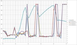
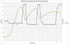
When an object (Z4MC) moves through air, the air provides an opposing force which can be measured as an increase in static air pressure. This is known as the “ram effect”. Everyone knows that this happens because when you stick your hand out of the window of a moving car you can feel the air against your hand. The faster you travel the greater the force. However, the increase in force does NOT increase in a linear fashion, but instead, it increases exponentially with increase in speed. The graph below shows how the increase in pressure occurs with an increase in speed, and the pink plots are from actual recordings that I’ve made, just to check that the theory works in practice!

When a car moves through air, the movement causes different air pressure zones around the entire car; some of these zones are at relatively higher static air pressure than ambient pressure, and such zones experience increases in pressure as shown in the graph above. The Z4MC’s OEM air intake system has been designed to utilise the increase in pressure that occurs with increase in speed by locating the mouth of the air-intake system in a zone of high pressure, just under the bonnet. I’ve previously datalogged the pressure inside the air-filter box during driving conditions and found that the pressure inside does relate to the speed and that pressures above ambient are seen. In real world driving, this means that the engine operating at any specific RPM will perform more efficiently at a higher speed in a higher gear, because the static air pressure will be higher for each fill of the cylinder, which means that more air can enter the cylinder so more fuel can be added, which in turn, increases the power output.
Although the OEM air-intake is well located to harness the “ram effect”, the system can be improved by providing even more air at higher than ambient pressure. When the engine is operating at higher RPMs, the engine is “draining” the zone of high pressure, so as engine speeds increase, the pressure of air starts to reduce. Therefore, if you can provide more air at higher than ambient pressure, to supplement the zone of high pressure where the OEM intake is located, then it is possible to partially reduce the “draining” of the original zone of high pressure. This has been the ethos of modifying the air intake of my Z3MC and so I wish to do similar modifications to my Z4MC.
Since a normally aspirated engine (S54) is an “air pump”, in order to get the engine to operate most efficiently, it’s important to ensure that the flow of air through the engine is as unobstructed as possible, on both intake and exhaust sides. So, as my starting point, I bought a pair of OEM silencers to modify.
I’d not opened a set of Z4MC silencers before, but from my experience of exhaust modding the Z3MC, I could “read” the construction method from looking at the weld marks on the silencers. I wanted to do all my “surgery” from the upper side of the silencers, so that my work would be invisible when the silencers were fitted to the car. So, I cut the largest window that I could, which would not affect the integrity of the silencer after I’d removed various parts from inside. The photos below show the process that I followed.
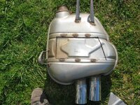
The window has been cut.
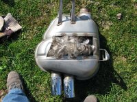
When I removed the window I thought Marilyn Monroe's head had been left inside!

In fact the inside of the exhaust is packed with fibre glass for sound deadening.
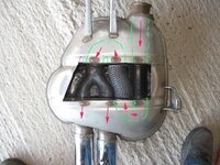
This photo shows the internal layout. I was surprised to find that the entire route of exhaust travel was piped through the box, whereas I was expecting the end chambers to be empty of pipe work.
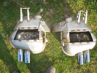
I removed all the pipe work in the central section and the "U" bends at both ends of the silencers. I then welded blanking plates over the holes into the end chambers so that the flow of exhaust is now "straight through" in the middle chamber. I welded the windows back to make the silencers leak-proof.
For the air intake, I want to increase the size of the area of the zone of high pressure, so I made a pair of scoops from aluminium with a neoprene pipe which interconnects them. The photos below show the process. I have measured the operating temperature of the radiator with an Infra-red thermometer (a great device for taking tyre temperatures for setting up suspension) to ensure that they don't impair the flow of air to the radiator.

Visible in trial stage during fabrication.
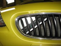
The interconnecting pipe visible at this stage.
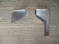
The parts.
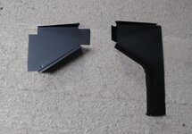
After painting
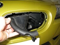
The OEM air intake has an upward facing "mouth" which means that air has to take a more tortuous route into the system than if it were not there. So I removed it. The photo below shows the part.
You can now see straight into the air intake system as shown below.
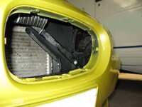

The finished parts.
During the process of fitting these mods, I've been datalogging to assess the advantage or disadvantage of any of them, but I've not been able to see any significant change which has been irritating the life out of me! :evil: I've been giving this problem considerable thought and I had a "Eureka Moment" a few days ago. The answer has been staring me in the face. So I have done the necessary mod and I took my car for a Dyno run yesterday and I believe I've cracked it!
