E85 / E86 BMW Z4 – Android tablet integration

markplant said:
Pin assignments at plug connector X18802 (white plug):
Could I ask were you got the pin info from for connector x18802,
Or a link if you have one thanks
Top job :thumbsup:

I found it in google. Most pinnings for X18802 were incorrect. This is correct one for Z4. Personally tested by tester.
If you have free wire (from used monitor you are going to install) just connect white plug and use tester in beep mode to ping thru wires on other end to find right wire for right pin: video wires are marked with red, green and blue label (center is + pins 1,3,5, shield is corresponding minus or ground these are pins 2,4,6- all these could be connected together), find wires linked to pin 8 and pin 9 and measure voltage (should be 12V). Other wires are not required (pin 7, pin 11).

You can find the same in board monitor installation spec in section 10 - circuit diagram (top middle of the page).
 
markplant said:
How do you get rid of the AVIN SOFTWARE buttons that appear on screen

After AVIN showing picture from board computer just touch screen one time and buttons will disappear, touch again and buttons will appear.
 
Plan to work and improve picture from board monitor in next days. Found out two more elements in LM1881 spec to reduce noise and cut crap from input signal.
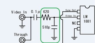
620Ohm resistor and 510pf capacitor.
Idea is to add few more elements on LM1881 pin 2 input.

According to LM1881 spec: Normally the signal source for the LM1881 is assumed to be clean and relatively noise-free, but some sources may have excessive video peaking, causing high frequency video and chroma components to extend below the black level reference. Some video discs keep the chroma burst pulse present throughout the vertical blanking period so that the burst actually appears on the sync tips for three line periods instead of at black level.A clean composite sync signal can be generated from these sources by filtering the input signal. When the source impedance is low, typically 75Ω, a 620Ω resistor in series with the source and a 510 pF capacitor to ground will form a low pass filter with a corner frequency of 500 kHz. This bandwidth is more than sufficient to pass the sync pulse portion of the waveform; however, any subcarrier content in the signal will be attenuated by almost 18 dB, effectively taking it below the comparator threshold.

uc?export=view&id=0B09H36dWQVCdZ3EtcHVfenpMQ3c.jpg

Result: Stuff above did not work. No improvement :driving:
But during processing I accidentally touched video wire and arrived to expectation :thumbsup:

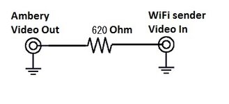
So finally I did the following: added 620 Ohm resistor between Ambery converter and WiFi sender on video cable center wire (just soldered it inside WIFI video sender video wire connector) and got what I was expecting.
I found out that by changing resistance (from 0 up to 1k) will change not only stability but also brightness etc. So there is place for experiment by trying 0 ohm -to 1K trimmer and by finding perfect resistance.

uc?export=view&id=0B09H36dWQVCdT3U3UW9kMHowcFU.jpg

After adding this resistor sync wire connecting delay on also probably not required as sync is catch immediately without any issues.

Ideally WIFI AVIN app requires improvements too to remember user choice:
1. save picture zoom on closure and restore picture zoom on opening
2. the same for showing/hiding buttons
 
js_online, where did you get the ambery and chip from . as I've hacked into my wiring today . but I soldered on phono leads an connected to a rgb to composite an then used the same WiFi sender.
Getting image on to screen but its slightly big slightly blocky and purple .
Converter was from Amazon
http://www.amazon.co.uk/gp/product/B00ATQ26PC?psc=1&redirect=true&ref_=oh_aui_detailpage_o00_s00
Getting a bit out of my depth :headbang:
Cheers for any help
 
markplant said:
js_online, where did you get the ambery and chip from . as I've hacked into my wiring today . but I soldered on phono leads an connected to a rgb to composite an then used the same WiFi sender.
Getting image on to screen but its slightly big slightly blocky and purple .
Converter was from Amazon
http://www.amazon.co.uk/gp/product/B00ATQ26PC?psc=1&redirect=true&ref_=oh_aui_detailpage_o00_s00
Getting a bit out of my depth :headbang:
Cheers for any help

LM1881 I purchased in local electronics store. As its relatively chip try one more.
Regarding Ambery:
Purchased on e-bay with name "e-video", item: "15Khz RGB RGsB RGBS to VGA XGA Converter Scaler". I do not see this item anymore. As I understood by communication this item was purchased directly from Ambery in US. I believe you can order also directly on Ambery site

Ambery is connected to 12V power.
Ambery is in NTSC mode.
Cable from X1812 (MK4) is connected to VGA 15pin D-SUB connector. I did not used internal on board connector (only taking green from it to pass to LM1881) as H/V sync on internal connector have resistor in between it and Sync H/V on VGA D-Sub input pin 13 Sync H/V (probably this is raising color change). So I am taking green video wire from connector on board to pass to LM1881 and passing back Syn H/V from LM1881 to pin 13 on D-Sub VGA connector.
Here I recommend you to check are you doing the same or not and also double check that you are passing Red Green and Blue from MK4 to correct corresponding pins on D-Sub 15. To find right wire on D-Sub I recommend you also ping thru (beep) with tester Red Green Blue on Ambery board with corresponding pins on Ambery D-Sub VGA to be 100% sure you use right wires on D-Sub (Red Green and Blue on D-Sub are linked directly with Red Green and Blue on board).
So check this page, pinning of Ambery is on the bottom.
If stuff above is not helping try to check Ambery converter at home by connecting different RGB source (for example DVD player at home( and simply passing composite to external monitor or tv).

Screen in WiFi video sender is bigger, I confirm this, so you need to zoom in by standard android method (moving 2 finger closer). I recommended developer to remember last user choice, so hopefully it will be included in next versions.
Sometimes picture little bit is not stable and shakes minimal. As I found this is issue of wifi video sender and re-opening app helps.

I hope in close future video in for android will be improved and standardized (VGA video in, HDMI video in etc) and I hope more devices will be available, so replacing only wifi video sender will solve all current issues and expecatations.

I am not sure, but I believe it is not good idea to connect the same RGB from MK4 to 2 sources (BMW board and Ambery) at the same time as signal will have noise.

And of course I wish you patience mate and idea will succeed one day. I was bearing monitor idea for 2 years, searching on google, reading this forum, reading another papers.
 
Thanks for that . I will try the pinch to zoom first as that's straight forward. An then see about getting the ambery. Thanks again
 
markplant said:
js_online, where did you get the ambery and chip from . as I've hacked into my wiring today . but I soldered on phono leads an connected to a rgb to composite an then used the same WiFi sender.
Getting image on to screen but its slightly big slightly blocky and purple .
Converter was from Amazon
http://www.amazon.co.uk/gp/product/B00ATQ26PC?psc=1&redirect=true&ref_=oh_aui_detailpage_o00_s00
Getting a bit out of my depth :headbang:
Cheers for any help

Actually checked your amazon link. This device is not compatible with current project - I do not see Sync input on it. This is just standard "RGB to Composite Video Converter" without sync input.
Believe me, I tried many devices from China and Europe until I found Ambery.

First of all Sync is implemented on Green in BMW (RGsB). In standard devices it is implemented on Blue (RGBs). Therefore you MUST Extract Sync from Green wire and pass it separately to Sync H/V (see my previous post, datasheet of LM1881 and article which provided step by step guide about LM1881 sync separator, 2 capacitors and resistor required for LM1881).
This is the main idea and the most complex and important part of it and you can't skip this.

Conclusion - if you expect the same result you should use the same devices and setup :wink:
 
Hi, guys!

first of I have to give big thanks for the awesome arduino+ sony tablet integration.
I have it done completely, but I have a major issue that I hope you will be able to resolve quickly!

Basically, on ignition the tablet doesn't move all the way up. If I manually move it to the maximum possition, then upon taking the key out the screen doesn't fully close down.
Please help, I have a perfect setup and I hate to have it ruined by this small issue!

Is there something in the code that might be wrong?

Here is a video of what is happening:
[youtube]https://www.youtube.com/watch?v=im4uoe5YdEk[/youtube]
https://www.youtube.com/watch?v=im4uoe5YdEk
Please, I would love a quick answer to this, so shoot me an email with the fix
[email protected]

THANKS!!!!
 
Svet88 said:
Hi, guys!
first of I have to give big thanks for the awesome arduino+ sony tablet integration.
I have it done completely, but I have a major issue that I hope you will be able to resolve quickly!
Basically, on ignition the tablet doesn't move all the way up. If I manually move it to the maximum possition, then upon taking the key out the screen doesn't fully close down.
Please help, I have a perfect setup and I hate to have it ruined by this small issue!

Hi!

As I understood from my setup this happens because stepper motor must be powered before running code. If motor is powered on ignition and code is run simultaneously you have result like this. In original BMW setup stepper motor is powered all the time.
This also happens in my car if car was not running for a long time (few weeks). I believe you can add also kind of physical timer relay for this to power on stepper motor before arduino runs code.

From code perspective I added delay already for initial monitor opening, you can increase DELAY_L from 500 millisecond higher to 1000 etc. to allow motor power up first.
Code:
int DELAY_L=500;    //long delay
...
void setup()
...
  //power on delay
  delay(DELAY_L); 
...

To see and debug counter value simply connect your arduino board to PC, open arudino software and Enable Serial Monitor by pressing Ctrl + Shift + M to see debug messages.
This line
Code:
 Serial.print("POS_CUR=");Serial.println(POS_CUR);
in code will print you counter value on screen movement.

Regarding maximum position - try to play with POS_MAX variable in code by increasing it to 11, 12, 13 etc:
Code:
float POS_MAX=10.7;       //monitor maximum position

Regarding manual movement by hand - as I described in code - "Positioning is not tracked if monitor is adjusted manually." Counter is tracking only in the moment monitor is moved by code (initial ignition open/close or buttons).
 
Is it possible for someone to put a kit together for those of us who have the factory pop up screen. Id love this, but would love to retain the radio and phone functionality.

Not that good with a solder iron myself, but woukd love a kit that we could put together ourselves..
 
Vanne said:
Is it possible for someone to put a kit together for those of us who have the factory pop up screen. Id love this, but would love to retain the radio and phone functionality.
Not that good with a solder iron myself, but woukd love a kit that we could put together ourselves..

All you need is described in this message.

Tablet setup:
1. Sony Xperia Z Ultra + Magnetic charge USB cable + Micro Usb cable (for sync)
2. Arduino R3 UNO + USB cable (for sync)
3. Timer relay
4. 12V relay (to enable arduino on ignition)
5. Converter 12V to 5V 3A

Radio and phone functionality is not touched. Nothing is touched except screen of original BMW setup.

This post describes setup to see video from board computer (MK4 without video module) on integrated Android tablet.
 
Any soldering required? The circuit for sync on green, do I have to make that or does it just plug into tvtowifi? I love how you hace done this, hat off. ;-)
 
Vanne said:
Any soldering required? The circuit for sync on green, do I have to make that or does it just plug into tvtowifi? I love how you hace done this, hat off. ;-)

As described in post. You need to solder LM1881 to extract sync from green. Also you need to solder BMW RGB video wires to 15pin D-SUB VGA connector as per Ambery specification.

Nothing in this project is just "plugin". But stuff is not complex. Everything is described in all details. You can ask assistance to make soldering work done in your region or this is great opportunity to learn solder your own ;)
 
Regarding initial monitor opening delay after ignition is turned on:

1. Define variable and set value (5000ms = 5 sec in this example):
Code:
int DELAY_INIT=5000;    //delay on ignition

2. Add delay in 2 places in code (setup section and loop section):
Code:
 if (ignState==LOW)   {
    //ignition 12V power is on 
    delay(DELAY_INIT);     
    ...
 
As I have failed trying to source a z4 nav loom, I'm considering retrofitting android tablet..

I have only a screen and a screen-less radio, plus my oem bmw business cd setup with amp and 10 speakers (logoc 7).
What I'd like to achieve is to have a tablet integrated with screen housin, which would have its funcionallity, as an AUX source, but would allow me to change tracks with mfsw, and would have a usb socket to use a pendrive as a music source.

What I will need except an xperia z, arduino, and all that stuff?
Probably some kind of mediabridge?
And does the mediabridge allow mixing sources in it? Meaning if you have a nav on tablet, and usb connected to mediabrigde, will it play it both simultanously?

Cheers,
McK
 
Hi there!

I was not satisfied with VIDEO quality from Board Monitor and how WiFI video sender operated so finally I got time to implement improvements.
WiFi video sender is replaced with EasyCap video capture device (6$ on AliExpress).

uc


EasyCap viewer app from GooglePlay is used to display video on Android (4$). According to developers app works only with certain chips - utv007(HTV600). I was lucky - EasyCap I ordered came with right UTV007 chip. Make sure to enable NTSC mode in settings and place button to NTSC mode on Ambery converter.

uc


The main challenge was to enable Host mode (USB on-the-go or OTG) on Tablet to make easy cap work. Only 4 wires are present in standard micro USB wire (Pins 1,2,3,5). For this purpose I created custom micro USB wire with all 5 pins soldered (including PIN 4 which is responsible for turning on Host mode).

uc


Host mode (OTG) is enabled on Tablet by connecting PIN 4 to the PIN 5 (GND). After Host Mode is on - Tablet is powering device connected to it (PIN 1 provides +5V), pins 2, 3 are transferring data.

So in my setup one more wire (from micro USB, PIN 4) was passed in parallel with standard micro USB wire to the point of Ambery Video converter. I added button (BLUE one the left bottom corner on image below) in the panel (where AUX socket is located) to turn on Board Monitor video (powers Ambery video converter, powers relay) when required (to do Settings - set time/date, Balance Audio, see Track number etc.).

uc


12V relay is added (to connect PIN4 with GND) to the same button to enable Host Mode on Tablet. In normal conditions Board Monitor button is turned off in my car to disable Host Mode on Tablet (otherwise EasyCap will drain battery as Phone powers it) and do not power Ambery video converter.

uc


Standard wire bunch on EasyCap was removed and I soldered 2 wires directly to socket to get video in signal. I also removed USB male connector from EasyCap and soldered by wires USB female connector, so I can use USB male from tablet directly.

Result are fantastic:
1. Stable video from board monitor
2. Right Corner is not cut
3. Video from board monitor appears on Tablet in the moment I turn on Board Monitor button on panel near AUX socket, as EasyCap automatically starts app in the moment Host Mode is enabled and EasyCap device recognized. EasyCap closes automatically after hiost mode is disabled and EasyCap is unpowered (blue button tuned off).

More pictures (including screenshots and video will follow).

PS I managed to do adjustments (connecting new micro USB connector to Tablet and passing thru gray wire from PIN4) without removing board monitor, by opening up board monitor top cover in car. This saved a lot of time.

uc


uc


uc


[youtube]2tQVCHr59vY[/youtube]
 
js_online said:
Hi there!

I was not satisfied with VIDEO quality from Board Monitor and how WiFI video sender operated so finally I got time to implement improvements...

Hi,
I'm looking to undertake this project in my E46 with MK4 Nav computer. I'm going to do it slightly different though in that I'm going to use an android dev board or box and a 6.5" 800x480 screen possibly this http://www.ebay.co.uk/itm/HDMI-VGA-...800718?hash=item3389892d4e:g:PRAAAOxy4dNSzPnR as it will be e perfect fit/replacement for my existing screen. This will allow the Nav output to be native without the need for the WiFi transmission or the android device present.

I'm posting on here as I've not been able to find any decent sources regarding the conversion of the Nav RGB output. What's got me confused is that you've stated that the sync is extracted from green however according to the pinout for the nav as shown here the sync signal is already separate? R(4) G(8) B(13) s(17) As far as I'm aware the MK4 Nav computers are all the same so could you clarify?

MK2_MK3_MK4_pinout.jpg
 
McKoval said:
And does the mediabridge allow mixing sources in it? Meaning if you have a nav on tablet, and usb connected to mediabrigde, will it play it both simultanously?

Cheers,
McK

Nope. they're mutually exclusive on the Denison and mediabridge.
Its something I'm trying right this very moment to resolve on my SkiPi, but currently to no avail. :thumbsdown:
 
Tungmeister said:
js_online said:
Hi there!

I'm posting on here as I've not been able to find any decent sources regarding the conversion of the Nav RGB output. What's got me confused is that you've stated that the sync is extracted from green however according to the pinout for the nav as shown here the sync signal is already separate? R(4) G(8) B(13) s(17) As far as I'm aware the MK4 Nav computers are all the same so could you clarify?

According to wiring diagrams I used pins 5, 6, 7 are for RGB and 14, 15, 16 for corresponding grounds. Sync is not present on MK4 and is present on TV tuner only. My setup is without TV tuner. If you have setup with tv tuner you should have sync.
Pinning in my MK4 was similar to X1313 and X1312 pinning in the doc attached (Only pins 1, 3, 10 were used on X1312 in my MK4).
http://www.bmwcarx.com/web/DocumentosBMW/BMWNavigationVideoandAudioInformation.pdf

I believe you should find proper wiring diagram for E46 to double check, I mean wiring diagram between MK4 and screen.
See example for Z4 on page 15 (see wiring between X1313 MK4 ---> X18802 Board Monitor).
http://www.bmwcarx.com/web/Document...ipamiento navegador profesional en ingles.pdf
 
Back
Top Bottom