Mojito, I'm posting for a little help. Here's where I am in 'cloning' your cool mod:
> Garmin DriveSmart 66 ready; back-up camera arriving tomorrow
> Wiring extensions are finished and ready for fitting into project box
> All old "soft touch" finish has been carefully removed, and re-paint is underway
> BT adapter is in hand
> New Business CD Headunit arrived in good shape from UK
BUT I have a couple of hurdles left and am looking for help.
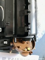
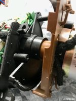
1) I foolishly paid little attention to preserving the rotational position of the stepper motor when I took apart the screen assembly. Do I need to precisely re-set the motor pinion-to-rack orientation ? I'm seeking confirmation that I don't need to worry. I hope the screen operates only upon motor steps from a zero point, with perhaps a slip clutch (or two ?) and needs no special orientation in re-assembly
2) My North American Garmin DriveSmart 66 came with a Garmin 12V power adapter and a cable that has an in-line "box" near the USB A connector end. The cable box is a receiver and/or antenna for HD and FM traffic information in NA. Further, the cable is supposed to connect into the Garmin-specific 12V adapter - it's not compatible with standard USB ports (which will force attempted PC sync). To use this cable I will need to cut-and-splice it to get it through the screen housing bushing. Did you have any USB cable issue ? Did you have to wire in a Garmin power adapter ?
Thanks for the inspiration . . . and thanks in advance for your help !
> Garmin DriveSmart 66 ready; back-up camera arriving tomorrow
> Wiring extensions are finished and ready for fitting into project box
> All old "soft touch" finish has been carefully removed, and re-paint is underway
> BT adapter is in hand
> New Business CD Headunit arrived in good shape from UK
BUT I have a couple of hurdles left and am looking for help.
1) I foolishly paid little attention to preserving the rotational position of the stepper motor when I took apart the screen assembly. Do I need to precisely re-set the motor pinion-to-rack orientation ? I'm seeking confirmation that I don't need to worry. I hope the screen operates only upon motor steps from a zero point, with perhaps a slip clutch (or two ?) and needs no special orientation in re-assembly
2) My North American Garmin DriveSmart 66 came with a Garmin 12V power adapter and a cable that has an in-line "box" near the USB A connector end. The cable box is a receiver and/or antenna for HD and FM traffic information in NA. Further, the cable is supposed to connect into the Garmin-specific 12V adapter - it's not compatible with standard USB ports (which will force attempted PC sync). To use this cable I will need to cut-and-splice it to get it through the screen housing bushing. Did you have any USB cable issue ? Did you have to wire in a Garmin power adapter ?
Thanks for the inspiration . . . and thanks in advance for your help !
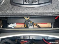
 I'll post a detail on which fuse I piggy baked onto.
")


 . Going to have to remove it all and spray with Matt black and Matt clearcote as you did Z4 Mariner. Lucky I have paint left over from refurbing my MF steering wheel!


