>

Retrofitting folding mirrors

Hi all,

Just thought I’d provide an update for anyone that has the pre wiring in their cars and want to retrofit the power fold mirrors.
My car is a jan 2004 build E85 and has the pre wiring as follows:
Drivers door switch to drivers door main coms plug
Drivers door coms plug to control module
Control module to passenger door coms plug

I bought the power mirrors and fitted as previously posted, I then bought the control module and fitted to the existing connection under the dash.
I then tested the system and found that the drivers door worked straight away but the passenger one would not.
Did some more investigation and found that although the car is pre wired for this the cabling in the passenger door is not present.
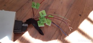
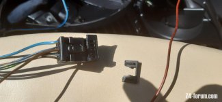
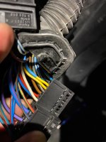
What I did was run two new cables from the coms port in the passenger door to the control switch in the door panel. Pins 14 and 15 in the coms port and pins 8 and 3 in the door switch.
Once connected both mirrors work perfectly.

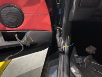
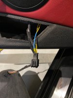
Did not need to strip the door just took off the bolt for the coms port switch, took out the window switch in the passenger door and used a coat hanger wire to feed the new wires through. 30 mins max from start to finish. Hope this helps people that want to do the retrofit and already have part pre wiring.
 

Attachments

  • C2CF20F7-ADC1-4A0E-84A9-C305E6EB01DB.jpeg
    C2CF20F7-ADC1-4A0E-84A9-C305E6EB01DB.jpeg
    451.7 KB · Views: 1,497
  • 711FE52A-A00D-4193-BB0E-9DB9485FB0E1.jpeg
    711FE52A-A00D-4193-BB0E-9DB9485FB0E1.jpeg
    395.9 KB · Views: 1,497
  • CF93F9E9-4ED0-4995-BD9A-985F3EC3BD7E.jpeg
    CF93F9E9-4ED0-4995-BD9A-985F3EC3BD7E.jpeg
    356.4 KB · Views: 1,497
Wookster78 said:
Oh really, I am sure there are two type of power mirrors ones that just fold and ones that have additional motors to dip when reversing, my mirrors have the duel function (11 wires on the harness vs 7 on the other type) when fitted will try Carly to code and report back if it functions

there are not! no dipping of mirrors when backing out. will not function regardless of how mush you wish/hope for it. :rofl:
 
I have nearly completed this project too.

I'd like to thank paulc_bkk and AngryZed for their photos and explanations. Pretty much everything I needed to know was gleaned from this thread and the BMW WDS wiring diagrams. It seems a bit daunting at first but when you go through it methodically, it all falls in to place.

https://bmwteka.com/wds/ru/e85/e9f279d9

I'd also like to thank Umfaan (Barry) for not only selling me the powerfold/dimming mirrors, door switches and control module but also (and without prompting) asking if I'd like the old door wiring harnesses and control module connector plug. This proved to be a great help since without these the job would have been more challenging, in particular the control module plug would be tricky to source.

20220325_134228.jpg

I started by pulling the outer shells of the mirrors off (silver) and swapping them with my current shells (Montego blue).

20220323_153623.jpg
20220323_153746.jpg
20220323_153739.jpg

I then stripped out my door loom and got ready to replace with the donor loom:

20220323_131636.jpg

I found that as the donor loom came from a pre-facelift car, it only had two wires going to the window motor plug, whereas post facelift looms have four wires. So, I swapped the window motor looms over. The BMW wiring connectors are really easy to de-pin and then re-insert into a new connector block.

20220324_134056.jpg

All I needed to do then was connect everything up ! Fortunately, as I now had two spare door looms with loads of different pin types, I was easily able to cobble together lengths of wires to go from the door hinge to the control module. You only need two wires for the passenger's side and three from the driver's side.

20220401_143030.jpg
 
The 12v power for the module, as stated by paul_bkk, comes from pin 8 of the purple X11004 block on the fuse board. Fortunately, one of the spare window power wires I was left with had exactly the right connector on the end and just pushed in (this is indeed protected by fuse 27). The blue/white wire here :

20220401_120444.jpg

A point of interest is that ALL driver's side window switches have the ability to add the powerfold button - while pulling the switches apart for cleaning and painting, I found that the contacts are in there, it just needs a hole drilling in the plastic casing and a suitable button inserting (maybe 3D printed):

20220324_170130.jpg

From TIS I have worked out that this button simply momentarily connects the blue/purple wire going into pin 12 of the control module to ground, which then either folds or unfolds the mirror. I'm not sure if folding on locking is available via coding, but if not I guess it could be done via a signal (and relay maybe) to momentarily ground this wire.

Here's another photo of the driver's door connector (X257). The white dots are where the new wires go into pins 13, 14, 15. Note that these connectors are held to the car by a bolt at the top, but they then must then be moved up by about 5mm to release a tab at the bottom. This one has that tab snapped off.

20220324_134221.jpg

Some more random photos:
20220324_135011.jpg
20220324_134418.jpg
20220323_130727.jpg
20220323_125529.jpg

In between snow showers, I'm currently fitting the control box in to place. It goes above and behind the fuse box (RHD car) and can be accessed more easily by lowering the GM5 module.

I'll then have a look at wiring up the electrochromic dimming, but I'm not too bothered about that yet.


If anyone wants any more photos or info, ask quick before I put everything back together !
 
It's a simple thing, but it saves me 2" each side in the garage ! 8)

[vimeo]695414314[/vimeo]
 
Hi there, I've got the control unit, mirror assemblies and door switch and am hoping to source the wiring from another forum member (bigwinn) who is breaking an early Z4 that should be pre-wired.

But we're having trouble tracking down the connector for the control module. Where exactly is the control module located - that would make it much easier to track down where the connector should be!

TIA. :thumbsup:
 
bigwinn said:
Is it this one?

Yes, that's exactly it :thumbsup:

Behind the fuses, just above the GM5 module, attached to the 'roof' of the passenger footwell.
 

Attachments

  • 20220325_134202.jpg
    20220325_134202.jpg
    77.7 KB · Views: 660
Today I got round to wiring up the dimming (electrochrome) wing mirrors. They take their power from the interior rear view mirror.

The housing round the mirror is in two halves and just unclips. The trim around the inside of the windscreen requires the four sun visor screws to be removed and it pulls away. The A-pillar trims then also just pull away.

20220421_125555.jpg

I inserted the two pairs of dimming power wires into the mirror connector as shown, then wrapped and routed the pairs of wires left and right along the top and down the a-pillars.

20220421_125605.jpg

They can be easily fed into the top of the footwell area by removing the air vents (2 screws), where I connected them to the mirror wiring.

20220421_125714.jpg

To test if the dimming works in the daylight you can switch the ignition on, switch the headlights on, then place a finger over the light sensor on the rear view mirror. To find it, feel round the rear left side of the mirror and it is in a small indentation.

Here is the relevant WDS wiring diagram:

Electrochrome wiring.jpg
 
A top tip to insert a pin/terminal into this type of connector block is to remove the small tab on top or bottom. The tab can easily be flicked out and re-inserted.
 

Attachments

  • 20220421_125656.jpg
    20220421_125656.jpg
    77.7 KB · Views: 570
Finally manage to get a set of complete retrofit kit from Wassup. Is anyone willing/able/available to install this for me? Happy to pay for the effort provided price is right. I am based in Essex and happy to travel up to 2/3 hours out. Thanks
 
Back
Top Bottom