Wiring in paddles

skmattwell

Active member
 London
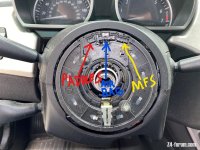
So I've merged a steering wheel with buttons and one with paddles to create one with both. All fairly straightforward after realising I'd need to add the buttons to the paddle steering wheel rather than vice versa to avoid mounting issues.

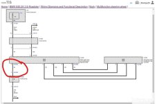
However the the paddles seem to occupy two pins of the 4 pin plug (on the right hand side in the photo) and the buttons occupy three pins (on the left).

IMG_20230314_154058338.jpg

Of course one of the wires can go into the empty slot, but the green wire is taking up the other space.

Does anyone know what the additional cable is? I'm guessing I just need to splice it into the green wire?
 
That’s odd, the paddles on my steering wheel (from a SMG) have a two pin plug which plugs into the slip ring. On a normal slip ring the two pin plug socket (to the left of the four pin plug socket) has no pins, I had to get one with pins - I thought you did too?
 
mac27040 said:
https://bmwteka.com/wds/en/e85/edd24545

Cheers mate!

Zedebee said:
That’s odd, the paddles on my steering wheel (from a SMG) have a two pin plug which plugs into the slip ring. On a normal slip ring the two pin plug socket (to the left of the four pin plug socket) has no pins, I had to get one with pins - I thought you did too?

Don't think I've explained quite right. So it does have the two pin plug and I bought a slip ring with the pins, but there are a further two wires come from the paddles, which I don't know there purpose or where they connect to
 
Hmm, there should be three wires (in a single flex) between the paddles, which are quite well concealed on an OEM wheel, but only two wires coming out according to the diagrams. Any chance you could take a zoomed out photo so we can see the bigger picture?
 
I believe you are going to need a different clock spring. You need one for a car that came with paddles, airbags and MF switches. the picture below is from my manual (no paddles of course) but you can see where the paddles would plug in if it was the correct clock spring.
 

Attachments

  • InkedInkedClock Spring.jpg
    InkedInkedClock Spring.jpg
    203.2 KB · Views: 304
Zedebee said:
Hmm, there should be three wires (in a single flex) between the paddles, which are quite well concealed on an OEM wheel, but only two wires coming out according to the diagrams. Any chance you could take a zoomed out photo so we can see the bigger picture?

Not my photo but explains what I mean better than any photo I can manage. So you can see the two wires with the pink plug, but there's an additional two wires coming from the paddles. I'm trying to figure out where they are meant to go, as the mfsw connector only has 1 pin unoccupied.

Screenshot_20230314-225911.png

BumpyZ4 said:
I believe you are going to need a different clock spring. You need one for a car that came with paddles, airbags and MF switches. the picture below is from my manual (no paddles of course) but you can see where the paddles would plug in if it was the correct clock spring.

I have the correct slip ring, my issue is more that there's more wires than pins
 
BumpyZ4 said:
Do you have an automatic or an SMG?

Steptronic automatic.

I think I've figured out these are both ground wires, so just need to figue out which pin/pins on the mfsw connector are for grounding
 
Don't know if this will help or make things worse.
This image is from an American ebay listing.

Screenshot_20230314-233441_Gallery.jpg
 
Usel said:
Don't know if this will help or make things worse.
This image is from an American ebay listing.

Screenshot_20230314-233441_Gallery.jpg

Although it's completely different colors, interesting to see the same colour in pins 1 and 2. Everything ive seen so far suggests these are both ground wires, I just can't find a wiring diagram to confirm it
 
You sure your green wire isn't blue?

It looks green in your photo but maybe your camera is colour blind.
 
Usel said:
You sure your green wire isn't blue?

It looks green in your photo but maybe your camera is colour blind.

You're right it is blue, my camera was just doing strange things!

This is probably the best image yet, seems to show the blue wire from the mfsw buttons soldered into one of the wires coming from the paddles, and the other wire from the paddles going into pin 1 of the mfsw plug

Screenshot_20230314-172329.png
 
The blue wire is also a ground wire. So, it is probably spliced with one of the paddle ground wires.
 

Attachments

  • InkedMFS Wiring.jpg
    InkedMFS Wiring.jpg
    70.3 KB · Views: 180
So do you think it would be best to wire:

1) blue from mfsw to paddles, paddles to pin 1 of mfsw plug

Or

2) All wires spliced into pin 1

Or do you think they would both work just the same?
 
What I would do is splice the blue wire (pin 1) from the MFSW and the black (?) wire paddle that is currently in pin 1 and leave them in pin 1 position. Leave the other black (?) wire that is currently on pin 2 on pin 2. I think that will work. Does below make sense?

Pin 1 - Blue MFSW & Black (?) Paddle (the one currently on pin 1)
Pin 2 - Black (?) Paddle (the one currently on pin 2)
Pin 3 - White MFSW
Pin 4 - Red MFSW
 
BumpyZ4 said:
What I would do is splice the blue wire (pin 1) from the MFSW and the black (?) wire paddle that is currently in pin 1 and leave them in pin 1 position. Leave the other black (?) wire that is currently on pin 2 on pin 2. I think that will work. Does below make sense?

Pin 1 - Blue MFSW & Black (?) Paddle (the one currently on pin 1)
Pin 2 - Black (?) Paddle (the one currently on pin 2)
Pin 3 - White MFSW
Pin 4 - Red MFSW

It does, thanks!
 
Back
Top Bottom