 France
Correct. Also the silicone doesn’t have much ‘cut-through’ resistance, so is prone to failure from nicks and small cuts. So it is a good move to protect it with flexible sleeving. The braided sleeve to protect the wiring bundle is a good solution, because it maintains flexibility. It should be possible to get it in different materials. Or as you said some ETFE or similar convoluted tubing. Both these are used in military and aerospace applications. ( eg undercarriage wiring)Unless you get the premium version I think the issue is that the sheaths wear easily…

You are using an out of date browser. It may not display this or other websites correctly.
You should upgrade or use an alternative browser.
You should upgrade or use an alternative browser.
Vanne roof, bit of a less fun post..
- Thread starter Vanne
- Start date
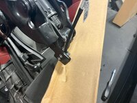
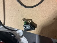

The magnet is in the hall sensor, you just need something metallic to hold over it.I know you can test these things by putting a magnet in front of it, but I don’t have a magnet handy
To be precise .. something made from ferrous metal ?The magnet is in the hall sensor, you just need something metallic to hold over it.
Thanks guys.. I’ll have a look for something metal.. this is gonna sound really dumb, but as I’ve been told, the only dumb question, is not to ask it… so with that in mind..
Where do I hold something metal to test these things?
Iam trying to see what lines up with this when it’s closed that is metal.. and I am drawing a blank..
I would think the center of the sensor right! The clips on the side are just for holing said sensor in place..
Unless it’s that copper sheeting bit at the end of the Hydrolic line? Is that what runs the sensor? (I’ll see if I can get a pic of it)
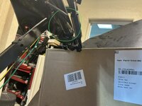
I’ve noticed all the other ends of the Hydrolic lines are a stainless looking fitting, unlike this one?
Where do I hold something metal to test these things?
Iam trying to see what lines up with this when it’s closed that is metal.. and I am drawing a blank..
I would think the center of the sensor right! The clips on the side are just for holing said sensor in place..
Unless it’s that copper sheeting bit at the end of the Hydrolic line? Is that what runs the sensor? (I’ll see if I can get a pic of it)
I’ve noticed all the other ends of the Hydrolic lines are a stainless looking fitting, unlike this one?
Last edited:

A magnet is a magnet.To be precise .. something made from ferrous metal ?
Each metal next to it will disturb the magnetic field. That's the intended functionality.

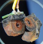
A very rusty HS, where magnetism got reduced due to inner corrosion.
The hall sensors generally are active components ( a chip is working inside) and no resistors. Specifically, they deliver 4 mA or 15 mA (according to their datasheets), representing logically LOW or HIGH. Every other assumption is not correct.One thing I am not sure about is the hall sensor in shell #2, should be 750 ohms closed and 20k ohms open, but I am getting no resistance from the sensor.. but then again, I have no idea how to test this thing.
Last edited:
Why not just mounting as intended?Found some screws/bolts.. 1.6mmx6mm, fits perfect. Hmm I had to cut it down to 3mm
View attachment 300460
Also superglued to the inside edge, so that puppy is going no where…
Taking off the little nut next to it,
pulling out the axis, pushing the new switch into the twol holes and heat up the pins with a hot air gun?
No screws, no glue is required.
That doesn't look as original from the factory. Somebody already was playing on this playground, that never fails.And then after I start undoing some of the ..tape… fark!,
Last edited:

 Scottish Borders
It must be the most butchered E89 ever..Thanks guys.. I’ll have a look for something metal.. this is gonna sound really dumb, but as I’ve been told, the only dumb question, is not to ask it… so with that in mind..
Where do I hold something metal to test these things?
Iam trying to see what lines up with this when it’s closed that is metal.. and I am drawing a blank..
I would think the center of the sensor right! The clips on the side are just for holing said sensor in place..
Unless it’s that copper sheeting bit at the end of the Hydrolic line? Is that what runs the sensor? (I’ll see if I can get a pic of it)
View attachment 300469
I’ve noticed all the other ends of the Hydrolic lines are a stainless looking fitting, unlike this one?

Thanks Robbie, I didn’t see that you could remove that little nut next to the bowed bit. Yep that would have helped a lot..
thanks.
And I’ll add that 4ma /15ma to my notes. Thanks for that, I was wondering why I wasn’t getting a reading on resistance.
Robbie, you’ve done this a lot.. I’ve read a lot of your posts. Thanks for helping out.
thanks.
And I’ll add that 4ma /15ma to my notes. Thanks for that, I was wondering why I wasn’t getting a reading on resistance.
Robbie, you’ve done this a lot.. I’ve read a lot of your posts. Thanks for helping out.
I recon so, but I guess the guys that were messing around with this previously didn’t have this forum to fall back on and ask questions, even super dumb questions.. hope to bring her back from the dead yet..It must be the most butchered E89 ever..

So again great forum this..
That doesn't look as original from the factory. Somebody already was playing on this playground, that never fails.
Ofcourse, you should have seen some of the other things I found in this car. the amount of screw ups previous persons messing with this car is crazy. (Pretty sure it wasn’t the owner, but the garage that the owner used..) That said, if you don’t know, and don’t have the time to investigate, then it would be really difficult to sort out what’s going on here, if not impossible. Luckily I had some time on a few layovers I could spend reading other posts (quite a few of yours too, though my German isn’t as good as it once was) and googling info, and a lot of help and hints from other members here too.
lol and then we have ANOTHER.. GREAT SUCCESS!!!!

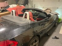
Works bloody great… windows too.. lolol
Man, as a project, that took way longer than I thought… but I learned a lot… and I learned also what not to do. But yeah, bloody great result.. thank you to all of you whom inspired and pepped me up during my lows and this win is as much yours as it is mine. Thank you again guys..
Freaking awesome… you lot are…
Now I just gotta put it all back together.. :/
as a side note i was a bit worried after plugging it all back in and putting shell 2 back in place, the blinken lights were doing the red dance again.. that scared me a bit, but it turned out that it was doing that as it didnt know where in the process it was in regards to the roof, so i closed the roof again... (and then i though, f**k bet it wont open again) and then the blinken red light stopped.
Pressed on the open roof button, and whola!!! roof opened up.. what a great thing, seeing that rear boot lid open up the wrong way is very impressive indeed..
I love it when a plan comes together.. donation made.

Works bloody great… windows too.. lolol
Man, as a project, that took way longer than I thought… but I learned a lot… and I learned also what not to do. But yeah, bloody great result.. thank you to all of you whom inspired and pepped me up during my lows and this win is as much yours as it is mine. Thank you again guys..
Freaking awesome… you lot are…
Now I just gotta put it all back together.. :/
as a side note i was a bit worried after plugging it all back in and putting shell 2 back in place, the blinken lights were doing the red dance again.. that scared me a bit, but it turned out that it was doing that as it didnt know where in the process it was in regards to the roof, so i closed the roof again... (and then i though, f**k bet it wont open again) and then the blinken red light stopped.
Pressed on the open roof button, and whola!!! roof opened up.. what a great thing, seeing that rear boot lid open up the wrong way is very impressive indeed..
I love it when a plan comes together.. donation made.
Last edited: