Track pad advice please

Lower said:
Brake pads with a higher coefficient of friction won't necessarily create more heat as the pressures applied by the pad to the disc for the same retardation is lower and can be applied for a shorter period. Logic tells you that the same amount of kinetic energy will be converted to heat but reality is different, certainly in regard of disc and pad temperatures.

etc.
Lower,

Thanks for your detailed input. :thumbsup:

I must say though that I find that last sentence hard to understand, because what you say suggests that The Law of Conservation of Energy is wrong :-o

I fully understand what you say about a ducted cooling system directed at the centre of the hub being possibly better than a scoop because the air inside the wheel arch swirls. However, if you look at the photograph of the Z4MC's disc-shield below, the top part of the shield slopes inwards at about 45degs, which I suspect interrupts the tendency of the air to swirl inside the inner part of the wheel which instead forces some of the air to pass through the vents in the shield to cool the brakes. The vanes inside the discs will also act as impellors, drawing air through the discs to cool both sides of the discs more equally.

I know a few owners remove the blanking plate from the rear of the OEM brake ducts in the bumper, in the belief that they're allowing more air through the ducts to cool the brakes, but I think this is a wrong move. The blanking plate is there to increase the velocity of the air passing through the brake ducts in the same way that putting your thumb over the end of a hose pipe creates a fast jet of water. I therefore suspect that the OEM brake ducts, complete with blanking plates, direct a stream of fast moving air directly towards the vented region on the OEM disc-shields. Obviously, when the wheels are facing forwards there is no direct "line of sight" from the brake ducts to the disc shields, so the air must have to travel around the inside of the tyre/wheel if it is to cool the brakes. What I'm trying to do with an auxiliary scoop is to put the lip of the scoop further inboard of the wheel/tyre, into that stream of fast moving air, so that more of it might be channelled through the vents, without any means of escape. I don't expect my first prototype to be the final design but I'll establish a baseline from it.

Obviously, a flexi-duct system would also need an outlet, so much of my scoop design can also be developed for that outlet.

I agree that stripes of heat paint are the best but, I've found that my IR thermometer recordings after immediately stopping after braking gives reliable comparative results (although not peak temperatures) and is a decent second-rate alternative.
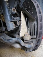
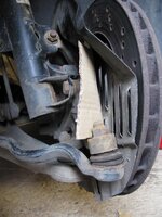
IMG_8455.jpg
 
exdos said:
I must say though that I find that last sentence hard to understand, because what you say suggests that The Law of Conservation of Energy is wrong :-o

I agree 100%. However, i did a lot of research into improving the braking performance of my S2000 and its proved to be the case. I did a number of tests on track with different pads and different discs using heat paint and with higher friction coefficient pads the brakes just ran cooler and by cooler i'm talking in excess of 100 degrees C. Its the peak temperature that is the key because by the time you've driven 100m down the road the discs have already cooled significantly from their peak but the pads haven't. Heat paint kits are pretty cheap.

exdos said:
I fully understand what you say about a ducted cooling system directed at the centre of the hub being possibly better than a scoop because the air inside the wheel arch swirls. However, if you look at the photograph of the Z4MC's disc-shield below, the top part of the shield slopes inwards at about 45degs, which I suspect interrupts the tendency of the air to swirl inside the inner part of the wheel which instead forces some of the air to pass through the vents in the shield to cool the brakes. The vanes inside the discs will also act as impellors, drawing air through the discs to cool both sides of the discs more equally.

I know a few owners remove the blanking plate from the rear of the OEM brake ducts in the bumper, in the belief that they're allowing more air through the ducts to cool the brakes, but I think this is a wrong move. The blanking plate is there to increase the velocity of the air passing through the brake ducts in the same way that putting your thumb over the end of a hose pipe creates a fast jet of water. I therefore suspect that the OEM brake ducts, complete with blanking plates, direct a stream of fast moving air directly towards the vented region on the OEM disc-shields. Obviously, when the wheels are facing forwards there is no direct "line of sight" from the brake ducts to the disc shields, so the air must have to travel around the inside of the tyre/wheel if it is to cool the brakes. What I'm trying to do with an auxiliary scoop is to put the lip of the scoop further inboard of the wheel/tyre, into that stream of fast moving air, so that more of it might be channelled through the vents, without any means of escape. I don't expect my first prototype to be the final design but I'll establish a baseline from it.

Obviously, a flexi-duct system would also need an outlet, so much of my scoop design can also be developed for that outlet.

I agree that stripes of heat paint are the best but, I've found that my IR thermometer recordings after immediately stopping after braking gives reliable comparative results (although not peak temperatures) and is a decent second-rate alternative.

IMG_8455.jpg
Putting your finger over the end if the hose increases the speed the water flows through the restriction, but the volume stays the same. In the case of cooling the velocity of the cooling air isn't so significant, its the quantity that matters.

The discs are designed to act as impellers, hence the curved cooling vanes. Getting as much air as possible to the centre of the hub to feed that impeller is key.

Those louvres in the dust shield are very restrictive. I run an engineering company and one of the products we manufacture is all about heating and cooling with air so i have some experience of the process and also of the sort of airflow you can get through those louvres which isn't much.

I don't know the specific dynamics of the airflow inside the wheel, but they are going to be complicated. Getting airflow to the hub via the duct and potentially removing those louvres in the heat shield is certainly going to make a big difference to disc cooling.
 
Exdos, re the blanking plates, what you are saying seems logical to me but what do you think the blanking plates are for? I mean why didn't they make the gap smaller in the first place.
 
exdos, et al

Check out these pictures for more ideas

Honda NSX front lower control arm
http://blogs.insideline.com/roadtests/2012/02/1991-acura-nsx-suspension-walkaround.html
1991_Acura_NSX_sus_fr_det_brk_deflector-thumb-717x478-114466.jpg


Porsche Cayman R front lower arm
http://blogs.insideline.com/straightline/2012/05/suspension-walkaround-2012-porsche-cayman-r.html
2012_Porsche_Cayman_R_sus_fr_det_brk_duct_a-thumb-717x478-120917.jpg
 
Lower said:
Putting your finger over the end if the hose increases the speed the water flows through the restriction, but the volume stays the same. In the case of cooling the velocity of the cooling air isn't so significant, its the quantity that matters.
The point is: a hot mass doesn't cool as fast in still air as it does if a stream of air moves over it, and the faster the air travels over it the greater the quantity of air that will make contact with the mass in a given time, which will speed up the rate it will cool by convection.

Lower said:
The discs are designed to act as impellers, hence the curved cooling vanes. Getting as much air as possible to the centre of the hub to feed that impeller is key.
Agreed, but since the rotors are impellors, they should also pull air to the centres of the hub through the vanes in the disc-shield.
 
daz05 said:
Exdos, re the blanking plates, what you are saying seems logical to me but what do you think the blanking plates are for? I mean why didn't they make the gap smaller in the first place.

I'm guessing here but I think that they are basically to stop water/crap splashing directly onto the inside surface of the discs and calipers, whereas the spokes of the rotating wheel must deflect most of this on the outside surface of the discs.
 
ga41 said:
exdos, et al

Check out these pictures for more ideas

ga41,

:thumbsup:
Thanks for those ideas. I was aware of the control arm system as per the Honda NSX and a few other cars, and had considered it, but since the Z4MC is already pretty close to the ground, to create something similar would mean the plate attachment would have to be too close to the road to "see" any direct air flow. Since there's already the OEM brake duct, it seems most logical to me, to exploit that first as much as I can. Likewise I prefer not to increase drag if it can be avoided.

I've made a revised scoop this morning in a lighter aluminium and got a part which weighs just 75gms.
 
Don't fret about unsprung weight if you're talking that light. 1mm of tire wear probably weighs less*

*edit: I of course meant "more".
 
All very interesting reading... Whilst there doesn't seem to be a ready solution for my immediate predicament as to what pads to buy, certainly it has given me some more ideas. Furthermore, this is now evolving in a great thread where the end point might be a more efficient means of keeping the brakes cool, so avoiding the problems I have had altogether :thumbsup:
At the risk of oversimplifying the problem, it strikes me that the volume of air that flows over the disk in a given time will determine the degree of cooling, so any mechanism of channelling more air into the wheel centre must confer some benefit. As such, a combination of ducting to collect air from beneath or in front of the car, with deflectors to direct this onto the disc and caliper is what is required.
I must say the Cayman R system looks very good, but I suspect a little vulnerable when the car grounds or a big rock comes into contact with it at speed.
 
I've found a relatively easy way of routing flexi-ducting to the brakes from a source of cold air in a zone of high pressure.

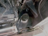
If you remove the front plastic undertray you will see at either side at the bottom of the radiator, two plastic panels which act as seals around the radiator. You can cut holes through these two panels through which you can pass the flexi-hose.

Access is easy on the right side as in this photo:

OSduct.jpg

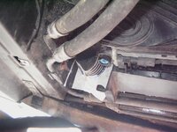
But is harder on the left because of the two hoses but only took a few minutes with a dremel. I stuck some masking tape on the panel and drew the aperture I wanted to cut, so that I could keep the cut neat.

NSduct.jpg


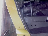
This photo shows the flexi-hose passing through the right panel.

OSUnderside.jpg


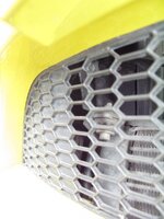
This photo shows the location of the inlet into the flexi hose. It is just behind the solid section of the lower bumper grill, adjacent to the oil cooler. I've not yet tested this area for pressure, but I expect that it is similar to the zone from which the air-intake inlet is located, and if so, then no special inlet other than a simple bellmouth in the panel which I've cut should suffice.

OSbumper.jpg


If the flexi ducting passes directly rearwards, it can then pass over the top of the transverse section of the front ARB and then be attached to the tie rod so that the outlet is located besides the hub. It will take about 100cms of ducting per side. I am using 50mm ducting.

As an aside, the central jacking point on the Z4MC is extremely useful for lifting the car onto axle stands on the car jacking points, more cars should have these.
 
nice work exdos!!! i love your stuff!!! dont forget to call when your at the daughters again :-) ive got some awesome stuff to show you :-)
 
exdos said:
Lower said:
Putting your finger over the end if the hose increases the speed the water flows through the restriction, but the volume stays the same. In the case of cooling the velocity of the cooling air isn't so significant, its the quantity that matters.
The point is: a hot mass doesn't cool as fast in still air as it does if a stream of air moves over it, and the faster the air travels over it the greater the quantity of air that will make contact with the mass in a given time, which will speed up the rate it will cool by convection.

Lower said:
The discs are designed to act as impellers, hence the curved cooling vanes. Getting as much air as possible to the centre of the hub to feed that impeller is key.
Agreed, but since the rotors are impellors, they should also pull air to the centres of the hub through the vanes in the disc-shield.

But we're not talking about a hot mass in still air. There is flow, so volume is the key ie m3/hr not velocity.

The discs are inpellors so do pull air ot the centre of the hub. However, just like the engine induction system, the more air you feed them, the better they can perform.
 
Lower said:
But we're not talking about a hot mass in still air. There is flow, so volume is the key ie m3/hr not velocity.

You've previous suggested that the air in the wheel arches is turbulent flow, which, ordinarily will not be effective in cooling the brakes, as a "hot mass", and I agree with this for most vehicles. However, what I'm suggesting is that the air exiting the OEM brake duct of a Z4MC, because of it's particular bespoke design, will be flowing similarly to a jet of water exiting a hosepipe when a finger is placed over the nozzle, because of the restrictor plate at the rear of the brake duct. As we both know, in the hose pipe scenario, the flow doesn't increase but the speed of the water exiting the hosepipe increases making it possible for the water to travel much further and be directed towards a specific location.

When I attempt any modding, I always attempt to understand what the clever engineers were seeking to achieve with their specific designs, and I am suggesting that a similar situation to the "finger over a hosepipe" principle has been designed by BMW engineers for the brake ducts by the specific configuration of the Z4MC''s OEM brake ducts to produce a fast moving "jet" of air exiting the brake ducts to overcome the normally expected turbulent air flow in the wheel arches so that an element of brake cooling will occur. The high velocity of this air will therefore travel further than just "pour" into the wheel arch to add to the turbulrence, and I would suggest the jet of air might travel around the inner side of the tyre/wheel by the Coanda Effect to reach the inside of the hub, to provide an increased VOLUME of air to do the necessary cooling. We both agree that even greater volume of air would be beneficial to increase the duty cycle of the brakes in track driving conditions and so we're discussing the possible ways of achieving this goal. I don't really see any difference between our opinions.
 
The point i'm trying to get across is that the overall same volume of air won't provide any additional cooling just because some of it is moving faster. 'Jetting' the same volume of air won't help, you just need more.

In addition, those louvres are typically used to let air out. The are particularly restrictive when flow is reversed. If they were designed to let air in to the disc the should be facing the other way and pushed in towards the disc.

The scoop design may actually hinder cooling if it works in the way you intend by reversing the designed air flow direction.
 
Lower said:
The point i'm trying to get across is that the overall same volume of air won't provide any additional cooling just because some of it is moving faster. 'Jetting' the same volume of air won't help, you just need more.

If you sit in a normal-sized sealed room with a fixed volume of air and you have a ceiling fan, you will feel cooler when the fan is switched on. Explain that.

Lower said:
In addition, those louvres are typically used to let air out. The are particularly restrictive when flow is reversed. If they were designed to let air in to the disc the should be facing the other way and pushed in towards the disc.
I understand that, but if they were used to be highly efficient at letting air into the disc, they would also allow the ready passage of dirt and water which would defeat the object of the "shield". At the end of the day, the Z4MC has been produced as a road car and not a race car with all the compromises that go with it when used as a track car. We're just looking at cheap and simple ways of improving the duty cycle. I do appreciate that you are offering experience and advice :thumbsup:

Lower said:
The scoop design may actually hinder cooling if it works in the way you intend by reversing the designed air flow direction.
You may well be right. One of the reasons that I like modding is to find out how things work and I am always prepared to be badly wrong because it helps me to learn and understand.
 
Beedub said:
nice work exdos!!! i love your stuff!!! dont forget to call when your at the daughters again :-) ive got some awesome stuff to show you :-)
Bee,

Thanks! :thumbsup:

Not forgotten. I've not been up there for a while.
 
exdos said:
If you sit in a normal-sized sealed room with a fixed volume of air and you have a ceiling fan, you will feel cooler when the fan is switched on. Explain that.

There is already flow. That is a given so your sealed room analogy is not appropriate. Again, the point i'm trying to get across is that you need to increase the volume of flow. Velocity for the same volume won't help.

I understand that, but if they were used to be highly efficient at letting air into the disc, they would also allow the ready passage of dirt and water which would defeat the object of the "shield". At the end of the day, the Z4MC has been produced as a road car and not a race car with all the compromises that go with it when used as a track car. We're just looking at cheap and simple ways of improving the duty cycle. I do appreciate that you are offering experience and advice :thumbsup:
.
I suspect that those louvres actually let the air out that would otherwise be trapped between the disc and the shield. Ducting air to those louvres may actually hinder cooling.
 
Lower said:
Again, the point i'm trying to get across is that you need to increase the volume of flow.

I've already taken your point on this.

Lower said:
Velocity for the same volume won't help.

The point that I'm trying to make is: if you have a fixed volume of flowing air it is far more effective at cooling a hot mass, if it is "brushed" as a "thin" stream over the hot mass. As we both know, for a given flow rate of air, the narrower the stream, the faster the air will travel. In turn, this faster air travelling over the hot mass will cause more turbulence/air movement in the surrounding air around the hot mass which will considerably aid cooling by causing movement in a much larger volume of air than in the direct flow.

Lower said:
I suspect that those louvres actually let the air out that would otherwise be trapped between the disc and the shield. Ducting air to those louvres may actually hinder cooling.


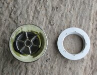
Since carefully examining the parts layout of my Z4MC and discovering a good location for two inlets for brake cooling, I am now preferring the flexi-ducted arrangement. I've already done this to my Z3MC, and done all the experimentation on that, so I know that it works well. I've decided to use two sink plug-holes as my inlet orifices which I've had lying around (I never chuck anything out!), as below.

IMG_8485.jpg


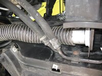
I've cut out the centre "star" to make a simple hole in the centre and these fit perfectly in the plastic panels through which they're inserted. The photo below shows the left side (most awkward location because of the pipes to the oil cooler) of my car with a piece of ducting fitted just for testing the route. The entire brake cooling system will cost me approximately £20 for 2 metres of 50mm neoprene ducting. My objective has been to demonstrate a really cheap alternative to a BBK for the Z4MC is easily attainable. :thumbsup:

Using the flow rate calculator here: http://www.1728.org/flowrate.htm a 50mm pipe at 50 mph will flow 2.6333 cubic meters per minute (92.944 cubic feet per minute) now how massive an air compressor would you need to deliver that output? 8)

IMG_8492.jpg
 
daz05 said:
Exdos, re the blanking plates, what you are saying seems logical to me but what do you think the blanking plates are for? I mean why didn't they make the gap smaller in the first place.
I believe the blanking plates have nothing to do with airflow. If the aim was to change the acceleration of air through the opening, then the whole duct profile would be changed to match to a smaller orifice. I believe the blanking plate is just to stop the majority of stones thrown off the tyres from making their way forward through the duct. Since I cut out the blanking plates, I have an order of magnitude more stones stuck between the join between the front bottom edge of the duct and the bumper moulding.
 
Back
Top Bottom