Radio not recognising AUX

benross

Member
I have installed an aux wire into the back of my bmw business cd head unit, in place of the cd changer.

When I cycle through the modes it doesn't come up with an AUX option, I googled it and it says I need to have the radio recoded so it knows it has an aux option, however I phoned my local bmw dealer who said it doesn't need it.

It obviously needs something as there isn't an aux option!

Please help!
 
nope.. no coding.

what wire did you use?
Does it have the required resistance between the + and - pins?

see the aux thread in my sig for details (pics are dead, but info on resistance etc is there)
 
sk93 said:
nope.. no coding.

what wire did you use?
Does it have the required resistance between the + and - pins?

see the aux thread in my sig for details (pics are dead, but info on resistance etc is there)

I used this one I bought off eBay,

http://m.ebay.co.uk/itm/131190606317

Shouldn't it just be plug and play
 
benross said:
sk93 said:
nope.. no coding.

what wire did you use?
Does it have the required resistance between the + and - pins?

see the aux thread in my sig for details (pics are dead, but info on resistance etc is there)

I used this one I bought off eBay,

http://m.ebay.co.uk/itm/131190606317

Shouldn't it just be plug and play

Sadly, this line will be the kicker here:

ebay said:
Aux MUST be available to select before purchasing this lead

Our headunits require a specific resistance between the two input pins to trigger the headunit to show aux as an available option.
Some bmws, like the newer minis, don't and have "aux" available even if there's no cable attached.

Looking at the pics of that cable, I don't see any cross-connection between the pins, so I highly doubt there's any crossover resistance.
You could double-check this by using a multimeter and checking if there's continuity between the two pins or not (when not connected to the headunit).

If there's not, then sadly, that cable won't work.. at least, not without modification.
 
If you have plugged it into your CD changer port then it wont show in the AUX, I think you need to just take it out and refit it in the AUX socket on the rear of the unit.
 
looking at the pics again however, I would think modifying the cable should be fairly straightforward.
Have a look at my guide bud, specifically regarding the capacitors and resistor, as that's the only bit you'll need to do.
you could easily splice this in on the "top" half of the cable (before the female RCA connectors).
 
Blueross79 said:
If you have plugged it into your CD changer port then it wont show in the AUX, I think you need to just take it out and refit it in the AUX socket on the rear of the unit.

I didn't see the bit regarding the CD changer port! :?
Yes - that won't work at all :thumbsup:
needs to go in the aux socket.
 
Blueross79 said:
If you have plugged it into your CD changer port then it wont show in the AUX, I think you need to just take it out and refit it in the AUX socket on the rear of the unit.

I have plugged it into the back of the head unit, there was a plug which I presumed was the cd changer, I took this out and plugged the new lead in.

It fitted correctly so I presumed that was where its meant to go.

I'll have a read of the posted guide now
 
sk93 said:
benross said:
sk93 said:
nope.. no coding.

what wire did you use?
Does it have the required resistance between the + and - pins?

see the aux thread in my sig for details (pics are dead, but info on resistance etc is there)

I used this one I bought off eBay,

http://m.ebay.co.uk/itm/131190606317

Shouldn't it just be plug and play

Sadly, this line will be the kicker here:

ebay said:
Aux MUST be available to select before purchasing this lead

Our headunits require a specific resistance between the two input pins to trigger the headunit to show aux as an available option.
Some bmws, like the newer minis, don't and have "aux" available even if there's no cable attached.

Looking at the pics of that cable, I don't see any cross-connection between the pins, so I highly doubt there's any crossover resistance.
You could double-check this by using a multimeter and checking if there's continuity between the two pins or not (when not connected to the headunit).

If there's not, then sadly, that cable won't work.. at least, not without modification.

I've had a look at the guide, could you give me a quick run through on what I would have to do to the lead I have bought to adapt it?

Can I just snip some of the wires and solder in the resistor/capacitor? If so what goes where?!

Thanks for your help, I was at my witts end.
 
benross said:
Blueross79 said:
If you have plugged it into your CD changer port then it wont show in the AUX, I think you need to just take it out and refit it in the AUX socket on the rear of the unit.

I have plugged it into the back of the head unit, there was a plug which I presumed was the cd changer, I took this out and plugged the new lead in.

It fitted correctly so I presumed that was where its meant to go.

I'll have a read of the posted guide now

there's two sockets it'll fit in.
depending on your car options, you may have one filled, both filled, or none filled.
regardless, it needs to go into the socket under the fuse slot.
if it doesn't fit in here, then you'll need to take the pins out of the plug, and manually attach each pin to the corresponding pin on the headunit.

it definately will NOT work if you plug it into the "B" (CD Changer) socket. (the one on the left, when you look at the back of the headunit).


in regards to modding the cable:

EDIT - wrong info,.. fixing!
 
bits you'll need as a minimum:

1x 300kΩ 0.6W Resistor - Maplin Part No: M300K - £0.16
2x 0.22uf Capacitors - Maplin Part No: WW56L - £1.12


If I was doing it on that cable, I'd do the following:

strip back a bit of the outer cable coverings from both cables in the "TOP" half of the cable, approximately half way down.
find the "positive" cable for each side (each side will have a ground and a positive, four wires in total - we are only interested in the positive wires, not the grounds)

again, strip back a bit of the covering from both positive wires so that you can access the bare wires beneath.
solder one end of a cap to each bit of bare positive wire (so you've got one cap attached to each wire - NOT one cap joining the two wires.)
then solder the resister inbetween both caps, linking them together.

you should then have the following:

wire->cap->resistor->cap->wire

reinsulate the cables and newly soldered joints.
insulate the resistors and caps.

job done.


if you're able to use a soldering iron in even just a minimal way, you'd get this done in ten minutes.
if you know what you're doing with a soldering iron, you'll do it in under two :thumbsup:
 
sk93 said:
bits you'll need as a minimum:

1x 300kΩ 0.6W Resistor - Maplin Part No: M300K - £0.16
2x 0.22uf Capacitors - Maplin Part No: WW56L - £1.12


If I was doing it on that cable, I'd do the following:

strip back a bit of the outer cable coverings from both cables in the "TOP" half of the cable, approximately half way down.
find the "positive" cable for each side (each side will have a ground and a positive, four wires in total - we are only interested in the positive wires, not the grounds)

again, strip back a bit of the covering from both positive wires so that you can access the bare wires beneath.
solder one end of a cap to each bit of bare positive wire (so you've got one cap attached to each wire - NOT one cap joining the two wires.)
then solder the resister inbetween both caps, linking them together.

you should then have the following:

wire->cap->resistor->cap->wire

reinsulate the cables and newly soldered joints.
insulate the resistors and caps.

job done.


if you're able to use a soldering iron in even just a minimal way, you'd get this done in ten minutes.
if you know what you're doing with a soldering iron, you'll do it in under two :thumbsup:


Right, Im pretty sure I plugged it into the right socket but ill check anyway. Thanks for the info, will pop down to my local Maplins now!

Will update with progress...
 
Right, I did as you said and modified the lead, it is still the same.

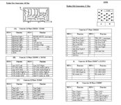
I spliced into pin 3&4 which according to your diagram are the two inputs (left & right)

Any ideas what's gone wrong? It's plugged into the right socket also (below the fuse)
 
Down in Sunny Devon, we call it banjo country!

I'm pretty sure I did a good job on the lead, so can't see why it isn't working.
 
Quick thought, do I need to remove the cd changer plug that's next to the aux plug I'm plugging in? Would that stop it showing an Aux on the modes?
 
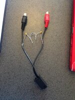
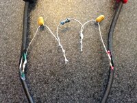
Heres a pic of the modded cable, if you could have a butchers and tell me if theres anything obviously wrong.

Oh, and Lidl have a great little soldering iron set for £6.99 at the mo! thought it would be crap but its pretty good.

IMG_8919_zpsd1cb29c5.jpg

IMG_8920_zps93eebc41.jpg
 
that looks bob on to me...
Definately going in the right pin holes too yeah?

very odd..

I may look to craft something up here, check it works, and fire it along to you
 
Back
Top Bottom