You are using an out of date browser. It may not display this or other websites correctly.
You should upgrade or use an alternative browser.
You should upgrade or use an alternative browser.
Radio not recognising AUX
- Thread starter benross
- Start date


SOLVED!
I went back to the start and checked my wiring, turns out I hadn't wired it correctly when I modded the wire.
I had wired the capacitors and resistor between the aux left and the aux ground. Not the aux left and right which it should have been. Wired it up and bingo! Aux was there!
Thanks for all the help, the guide was spot on, although I think ordering the lead off eBay and modding it was easier (when done correctly!) than starting from scratch.
Thanks again,
Going to listen to some tunes in my car!
Cheers
benross said:SOLVED!
I went back to the start and checked my wiring, turns out I hadn't wired it correctly when I modded the wire.
I had wired the capacitors and resistor between the aux left and the aux ground. Not the aux left and right which it should have been. Wired it up and bingo! Aux was there!
Thanks for all the help, the guide was spot on, although I think ordering the lead off eBay and modding it was easier (when done correctly!) than starting from scratch.
Thanks again,
Going to listen to some tunes in my car!
Cheers
huzzah!
I have just finished tearing mine out of the car however, to check I was right lol.
Best go put it back in now then

sk93 said:benross said:SOLVED!
I went back to the start and checked my wiring, turns out I hadn't wired it correctly when I modded the wire.
I had wired the capacitors and resistor between the aux left and the aux ground. Not the aux left and right which it should have been. Wired it up and bingo! Aux was there!
Thanks for all the help, the guide was spot on, although I think ordering the lead off eBay and modding it was easier (when done correctly!) than starting from scratch.
Thanks again,
Going to listen to some tunes in my car!
Cheers
huzzah!
I have just finished tearing mine out of the car however, to check I was right lol.
Best go put it back in now then
Thanks for all the help, sorry you've had to mess with the car again! I did come straight in and post once I'd seen the aux appear!
It confuses me as to why its made like that, in most cars it either has an aux setting on the modes or it doesn't. How soldering in a few components can activate a hidden mode is beyond me!
Hello everyone,
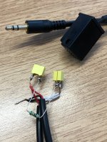
Ive read this discution and tried to make my own aux cable. I Took 3.5 from both sides, cut one side and made like it was said - wired the capacitors and resistor between the aux left and the right, kept the ground alone. Then i connected those three wires to the pins 3, 4, & 10 - 3 and 4 was right and left, 10 was ground. And there was no aux mode still.
Im adding pictures what Ive managed to do, to ask you guys, is there something Ive done wrong?
check with a multimeter the resistance across the left and right channels, ensuring it's around 300k Ohms.
Ground is unimportant at this point, as it's actually just the resistance between left and right that will trigger AUX appearing.
If it doesn't show resistence, try running some spare wire from the stereo to the resistor/cap bridge, then back to the stereo (effectively cutting out your cabling entirely) and check that works.
if that doesn't work, you've likely got a defective cap / resistor.. time to check / replace them individually.
if that does work, then you've got a break/bad join in your cabling.
let me know")
Ground is unimportant at this point, as it's actually just the resistance between left and right that will trigger AUX appearing.
If it doesn't show resistence, try running some spare wire from the stereo to the resistor/cap bridge, then back to the stereo (effectively cutting out your cabling entirely) and check that works.
if that doesn't work, you've likely got a defective cap / resistor.. time to check / replace them individually.
if that does work, then you've got a break/bad join in your cabling.
let me know
Hi don't know if anyone will see this as its looks like a very old thread but I've tried this and am not having any luck. What's confused me is the comment about metering between the left and right to check the resistance. Surely the caps prevent any resistance showing when metered?! I am not getting a reading although all the components are reading fine individualy. I wouldn't expect a resistance reading with the caps there blocking any dc.
Could someone please explain this?

Could someone please explain this?
Further to my last post. I had a look online as I couldn't understand how a dc resistance reading could be obtained between left and right channels with a cap either side. I found the OEM wiring diagram for e85 aux install and the caps are in series, one for left Chanel one for right with the resister across left and right channels closest to the head unit, before the caps. This makes sense as the caps are wired as coupling/decoupling caps and the resistance can be 'seen' by the head unit. In short, it worked in mine where the other way of wiring didn't. If anyone else is having problems getting aux to show, get in touch and I can send the OEM install sheet. I may try and post it under OEM aux install circuit diagram or something like that.


Hoping there is still some life in here
Before i go any further, i promise, i have read the whole thread from back to front, upside down, and round about. I have connected the aux cable in the right slot in the back, i have soldered in a 300k ohm resister between L and R, and used capacitors too (2x on each in parallel as i origionally bought + - ones so swapped them out). But i am getting no where. I have run a multimeter across the L R to make sure i am getting resistance, and i am, of 300k ohms.
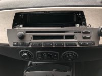
Basically, i plug it in, get FM / AM and CD but no AUX anywhere, ideas?
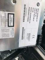
2004 BMW 3.0i SE with Business headunit.
Images attached.
Any help would be greatly appreciated.
Before i go any further, i promise, i have read the whole thread from back to front, upside down, and round about. I have connected the aux cable in the right slot in the back, i have soldered in a 300k ohm resister between L and R, and used capacitors too (2x on each in parallel as i origionally bought + - ones so swapped them out). But i am getting no where. I have run a multimeter across the L R to make sure i am getting resistance, and i am, of 300k ohms.
Basically, i plug it in, get FM / AM and CD but no AUX anywhere, ideas?
2004 BMW 3.0i SE with Business headunit.
Images attached.
Any help would be greatly appreciated.
Attachments
If it’s any consolation I’m having the same problem.
robertboeke
Member
Not sure how old this is, but thanks for sharing this worked perfectly for me!craigbeal said:1FB16C00-23D6-42DE-9FB1-288B74221BB6.jpeg41BA0C88-4410-4BC6-995B-073475A28BA5.jpeg12D1DFC3-168D-4D8A-AC5B-D4AEEF96CBAF.jpeg
 California
I am installing an after market Android unit to replace the top up Nav display. It uses the aux to play the audio through the original head unit. However, when i connect the aux cable the aux option disappears from the radio. I have not yet added the resistors and capacitors. Do you all think that will do the trick?
Assuming the capacitor and resistor goes between the red and white cable on the standard BMW cable to the back the OEM headunit
Assuming the capacitor and resistor goes between the red and white cable on the standard BMW cable to the back the OEM headunit