A small project that I’ve been waiting on delivery of the steering wheel came together today.
I’ve always liked the MFSW features on the X5 and with the law getting ever harder on hands free phones I wanted to prepare the Z4 for a Bluetooth retrofit. I also liked the idea of a paddle shift control for the auto box. Not to make an awesome track car but just an alternative way to change gear and IMHO get the best out of the sport mode in the box.
I was lucky to be able to source a wheel of a fellow board member in the US and finally received it after a long series of US/UK postal delays.
I’m not going to give a really detailed write up here because much is similar to so many write ups of retrofit on other boards for other BMW’s so will give a short review and few photos of what I did.
WARNINGS
Firstly this project involves removing the steering wheel airbag. You MUST disconnect the battery for at least 20 minutes before touching it and adhere to BMW safety procedures. I cannot accept any responsibility for anyone doing anything stupid and if you’re unsure – walk away now…..
Secondly you are tapping into the electronics of the gearbox. You must use appropriate tools to avoid any electrical earthing in the circuits. No mains soldering irons or nylon underwear...
So this whole project boils down to 4 wires – that’s all really
You need 2 for the radio/telephone side and 2 for the paddle shift.
Bits you need:
New mount if you do not have a late model with the extra 2 pins part 61.31.8.379.091 (I did identify spare pins in the existing mount but frankly it’s not worth risking using them when they are in the same plug as the airbag circuit)
Retrofit cable 61.12.0.394.848 (This is not listed on any system but is a special order from Germany and is a part of the official retrofit kit, without all the expense)
A pc reset 2 pin connector and various bits of wire, heat shrink wrap, zip ties, etc.
New Mount

Note extra 2 pin connector on left

Harness

Reset switch used for 2 pin connector

Test fitted in rear of mount

I also found the BMW retrofit instructions an enormous help with their wiring diagram.
So here we go:
Battery disconnect – 30 minute coffee break….
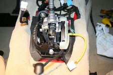
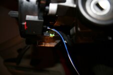
Dive into the gear shift selector and find the small 4 pin connector fastened to the side of the shifter. Tap into it with 2 wires and solder on 2 leads, one to each of the 2 central pins out of the 4 (non electric soldering iron so you don’t damage the electronics with any grounding or voltage. We can sort which is up and down later by reversing the column connection. Run these leads around to the column.
If the car were connected and running you could now shift up and down a gear simply by grounding either of these wires.
Back to those wires later
Turn to the column:
lower cowling off
Remove the airbag
Disconnect the various switch leads
Undo the central steering nut but don’t use the column lock to prevent the wheel turning and get the wheel out
4 torx bolts and off with the old steering ring
1 more torx screw and you can pull the instrument binnacle out and undo its connector
Top cowling is one more screw and pivots up and out the way
Original wheel – note pins missing on left

Next we need to run the new loom from the LCM to the back of the mount.
Reaching through the instrument binnacle void you can disconnect the LCM connector and identify the pins /wires to hook up to. This is the tricky bit as its some 50 wires to choose from, unless you’re a post 09/03 car then I believe this is already done.
Instrument binnacle out for access to LCM - through to right hand side

This the hardest bit identifying the right pins and wires to connect to
You need to join these using the harness and supplied connector:
Connector X10170 Pin 10 to connector X12 Pin 27
Connector X10170 Pin 9 to connector X12 Pin 21
BMW supplied connectors

Connector ready to break into with its cover removed

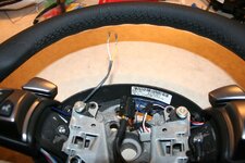
And at the steering wheel end we join into the green connector with 2 new sockets. You remove a cover off the connector and the 2 new leads slide into vacant slots 9&10 (note the shifter wires in blue and white ready for the paddle shift)

OK – remember those 2 leads you ran from the shifter. Work those up the column zip tying to the existing loom and solder in the 2 pin connector lead/plug.
That’s your 4 wires taken care of….
At the bench move your indicator and wiper switches over to the new mount, bolt it to the column and connect everything up. Your 2 pin connector goes in the new mounts 2 pin socket (reverse this to correct up/down if you get it the wrong way around) and of course the MF is in the existing green plug.
New mount with switches fitted ready to fit to column

Nearly there

Refit the instrument binnacle, top and bottom cowling, fasten the wheel and torque up.
Leads all plugged in

Connect the 3 sets of wires to their respective sockets, reconnect the airbag. (This always frightens me for no apparent reason other than things that are designed to explode might just do that)
Clip the airbag back in and reconnect the battery
The end result

Test
You should now be able to control the radio volume and station from the steering wheel
(If bluetooth were int he car I would hope that picked up too)
Test drive next. Shifter in sport and you should be able to cycle up and down the box with the shifter or the steering wheel paddles.
Proper test drive next. traffic free road - Sh*t this really works. Big grin as you go up and down the box for no real reason… Pull for up, push for down.
Almost instant reaction, no software hesitation allowing downshift instantly almost to the rev limit. Upshift just as easy, overshifting upwards correcly being refused and then dropping to an appropriate gear. This is smooth, intuitive and fun.
Driving experience is vastly improved bringing alive the steptronic, adding a fun factor and a safetly aspect of not messing with manual radio tune buttons ont he fly. :driving:
That’s it just a 4 wire project


My thanks go to the various members who chipped in and answered questions and provided links to support information
I’ve always liked the MFSW features on the X5 and with the law getting ever harder on hands free phones I wanted to prepare the Z4 for a Bluetooth retrofit. I also liked the idea of a paddle shift control for the auto box. Not to make an awesome track car but just an alternative way to change gear and IMHO get the best out of the sport mode in the box.
I was lucky to be able to source a wheel of a fellow board member in the US and finally received it after a long series of US/UK postal delays.
I’m not going to give a really detailed write up here because much is similar to so many write ups of retrofit on other boards for other BMW’s so will give a short review and few photos of what I did.
WARNINGS
Firstly this project involves removing the steering wheel airbag. You MUST disconnect the battery for at least 20 minutes before touching it and adhere to BMW safety procedures. I cannot accept any responsibility for anyone doing anything stupid and if you’re unsure – walk away now…..
Secondly you are tapping into the electronics of the gearbox. You must use appropriate tools to avoid any electrical earthing in the circuits. No mains soldering irons or nylon underwear...
So this whole project boils down to 4 wires – that’s all really
You need 2 for the radio/telephone side and 2 for the paddle shift.
Bits you need:
New mount if you do not have a late model with the extra 2 pins part 61.31.8.379.091 (I did identify spare pins in the existing mount but frankly it’s not worth risking using them when they are in the same plug as the airbag circuit)
Retrofit cable 61.12.0.394.848 (This is not listed on any system but is a special order from Germany and is a part of the official retrofit kit, without all the expense)
A pc reset 2 pin connector and various bits of wire, heat shrink wrap, zip ties, etc.
New Mount

Note extra 2 pin connector on left

Harness

Reset switch used for 2 pin connector

Test fitted in rear of mount

I also found the BMW retrofit instructions an enormous help with their wiring diagram.
So here we go:
Battery disconnect – 30 minute coffee break….
Dive into the gear shift selector and find the small 4 pin connector fastened to the side of the shifter. Tap into it with 2 wires and solder on 2 leads, one to each of the 2 central pins out of the 4 (non electric soldering iron so you don’t damage the electronics with any grounding or voltage. We can sort which is up and down later by reversing the column connection. Run these leads around to the column.
If the car were connected and running you could now shift up and down a gear simply by grounding either of these wires.
Back to those wires later
Turn to the column:
lower cowling off
Remove the airbag
Disconnect the various switch leads
Undo the central steering nut but don’t use the column lock to prevent the wheel turning and get the wheel out
4 torx bolts and off with the old steering ring
1 more torx screw and you can pull the instrument binnacle out and undo its connector
Top cowling is one more screw and pivots up and out the way
Original wheel – note pins missing on left

Next we need to run the new loom from the LCM to the back of the mount.
Reaching through the instrument binnacle void you can disconnect the LCM connector and identify the pins /wires to hook up to. This is the tricky bit as its some 50 wires to choose from, unless you’re a post 09/03 car then I believe this is already done.
Instrument binnacle out for access to LCM - through to right hand side

This the hardest bit identifying the right pins and wires to connect to
You need to join these using the harness and supplied connector:
Connector X10170 Pin 10 to connector X12 Pin 27
Connector X10170 Pin 9 to connector X12 Pin 21
BMW supplied connectors

Connector ready to break into with its cover removed

And at the steering wheel end we join into the green connector with 2 new sockets. You remove a cover off the connector and the 2 new leads slide into vacant slots 9&10 (note the shifter wires in blue and white ready for the paddle shift)

OK – remember those 2 leads you ran from the shifter. Work those up the column zip tying to the existing loom and solder in the 2 pin connector lead/plug.
That’s your 4 wires taken care of….
At the bench move your indicator and wiper switches over to the new mount, bolt it to the column and connect everything up. Your 2 pin connector goes in the new mounts 2 pin socket (reverse this to correct up/down if you get it the wrong way around) and of course the MF is in the existing green plug.
New mount with switches fitted ready to fit to column

Nearly there

Refit the instrument binnacle, top and bottom cowling, fasten the wheel and torque up.
Leads all plugged in

Connect the 3 sets of wires to their respective sockets, reconnect the airbag. (This always frightens me for no apparent reason other than things that are designed to explode might just do that)
Clip the airbag back in and reconnect the battery
The end result

Test
You should now be able to control the radio volume and station from the steering wheel
(If bluetooth were int he car I would hope that picked up too)
Test drive next. Shifter in sport and you should be able to cycle up and down the box with the shifter or the steering wheel paddles.
Proper test drive next. traffic free road - Sh*t this really works. Big grin as you go up and down the box for no real reason… Pull for up, push for down.
Almost instant reaction, no software hesitation allowing downshift instantly almost to the rev limit. Upshift just as easy, overshifting upwards correcly being refused and then dropping to an appropriate gear. This is smooth, intuitive and fun.
Driving experience is vastly improved bringing alive the steptronic, adding a fun factor and a safetly aspect of not messing with manual radio tune buttons ont he fly. :driving:
That’s it just a 4 wire project
My thanks go to the various members who chipped in and answered questions and provided links to support information


