As promised, here is a small how-to on the 'Phantom' Side Indicator clone I made.
Let's start with the BOM (Bill Of Materials):
WS2812 5050 LED Strip 60 leds/m 0.5m - www.ebay.co.uk/itm/272910838998 --> £4.49 (This is enough to complete both lenses, I used 14 per side)
Arduino Nano x 2 - https://www.ebay.co.uk/itm/262677405087 --> £6.00
3 Pin JST x 2 (You can buy 4 pack for the same price of 2 individuals) - http://www.ebay.co.uk/itm/152282668196 --> £2.99
Some wire (I have loads kicking around so didn't buy any... you don't need much)
Total Cost: £13.48
Software:
'Arduino IDE' (Free) --> https://www.arduino.cc/en/Main/Software
I did also 3D Print myself 2 parts to help, but these aren't 'required', as I'm sure many could fashion their own holder of sorts and solder directly to the bulb socket if they wanted. Or I could provide the parts for a small material cost.
Wiring:
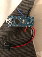
In the picture above, VIN and GND goto the 3D Printed W5W/T10 male plug to fit into the socket
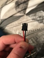
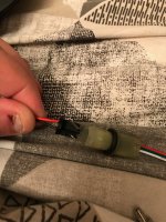
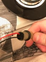
5V goes to the positive of the LED strip, GND to the negative, and D3 (Digital Pin 3) goes to DIN or DI (Digital In) of the LED Strip. All connections to the LED Strip are via the 3 Pin JST connection. On my JST connectors, I used the RED wire as the 5v Positive, the WHITE wire as the GND and the GREEN middle pin as the DI/DIN pin.
How-To
First thing you need is a flat headed screwdriver or a metal spudger. I used this tool:

I then started at the locating tab and worked my way around the lens. Inset the edge of the spudger into the edge of the lens and you can lever the lens up. You will hear it crack and creak as you work your way around the lens
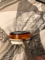
With minimal effort going all round the lens, the lens cover will separate and come off
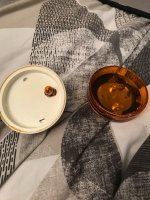
Next, I took my 3D Printed part and wrapped the LEDs around like so
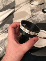
I then placed into the Lens...
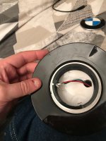
I then proceeded to program the Arduino, and placed it also into the lens in the middle of the 3D Printed part
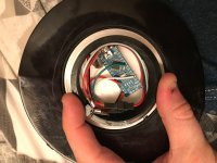
Next thing was to connect a 12v source and make sure the lens animated as intended.
NOTE: It is important to check your polarity especially when connecting to the car indicator plug. If you connect the +ve and -ve the wrong way round you're likely to destroy the ardunio
[youtube]Uq2_nLSnWyc[/youtube]
Once happy, you can now glue the lens back together and fit
Additional Information
A few things to note. Depending on the brand / quality of the LED strip, when they first power up they *may* flash white. One may flash or the whole strip will, it's hard to know for sure the behaviour. This is "normal" as for a split second, the Addressable LEDs do not know their state (eg, on or off) and will default to one or the other at random.
The Arduino has a bootloader in order to make it easier to write your programs to the board. This means there is roughly a 1 second delay. To overcome this you would need to build an Arduino ISP and upload the sketch via the ISP Programmer. What that does, is it over writes the bootloader (effectively removing it) and makes the code start instantly. This of course would incur an additional cost of about £7 plus the skills to build the ISP circuit. (For more information, see here: http://glumb.de/en/arduino-as-isp-to-change-the-bootloader - includes diagram to build your own)
On that note... should anyone wish, I'm more than happy to offer an exchange service as such... you send me an arduino nano, I'll send it back flashed without the code, without a bootloader.
Files
3D Printed Lens Mount: http://download.myz4.co.uk/download/961542d568e87cf12d25a051c44d1fcc.html
3D Printed W5W/T10 Male Socket: http://download.myz4.co.uk/download/a2ffddeebb62ff09b836271e1730e783.html
Arduino Code: http://download.myz4.co.uk/download/3eb67d331c4454fa5ce9b3a70b4df9d8.html
Any questions get in touch. 8)
** Download Links updated 14th April 2019 **
Let's start with the BOM (Bill Of Materials):
WS2812 5050 LED Strip 60 leds/m 0.5m - www.ebay.co.uk/itm/272910838998 --> £4.49 (This is enough to complete both lenses, I used 14 per side)
Arduino Nano x 2 - https://www.ebay.co.uk/itm/262677405087 --> £6.00
3 Pin JST x 2 (You can buy 4 pack for the same price of 2 individuals) - http://www.ebay.co.uk/itm/152282668196 --> £2.99
Some wire (I have loads kicking around so didn't buy any... you don't need much)
Total Cost: £13.48
Software:
'Arduino IDE' (Free) --> https://www.arduino.cc/en/Main/Software
I did also 3D Print myself 2 parts to help, but these aren't 'required', as I'm sure many could fashion their own holder of sorts and solder directly to the bulb socket if they wanted. Or I could provide the parts for a small material cost.
Wiring:

In the picture above, VIN and GND goto the 3D Printed W5W/T10 male plug to fit into the socket


5V goes to the positive of the LED strip, GND to the negative, and D3 (Digital Pin 3) goes to DIN or DI (Digital In) of the LED Strip. All connections to the LED Strip are via the 3 Pin JST connection. On my JST connectors, I used the RED wire as the 5v Positive, the WHITE wire as the GND and the GREEN middle pin as the DI/DIN pin.
How-To
First thing you need is a flat headed screwdriver or a metal spudger. I used this tool:

I then started at the locating tab and worked my way around the lens. Inset the edge of the spudger into the edge of the lens and you can lever the lens up. You will hear it crack and creak as you work your way around the lens

With minimal effort going all round the lens, the lens cover will separate and come off

Next, I took my 3D Printed part and wrapped the LEDs around like so

I then placed into the Lens...

I then proceeded to program the Arduino, and placed it also into the lens in the middle of the 3D Printed part

Next thing was to connect a 12v source and make sure the lens animated as intended.
NOTE: It is important to check your polarity especially when connecting to the car indicator plug. If you connect the +ve and -ve the wrong way round you're likely to destroy the ardunio
[youtube]Uq2_nLSnWyc[/youtube]
Once happy, you can now glue the lens back together and fit
Additional Information
A few things to note. Depending on the brand / quality of the LED strip, when they first power up they *may* flash white. One may flash or the whole strip will, it's hard to know for sure the behaviour. This is "normal" as for a split second, the Addressable LEDs do not know their state (eg, on or off) and will default to one or the other at random.
The Arduino has a bootloader in order to make it easier to write your programs to the board. This means there is roughly a 1 second delay. To overcome this you would need to build an Arduino ISP and upload the sketch via the ISP Programmer. What that does, is it over writes the bootloader (effectively removing it) and makes the code start instantly. This of course would incur an additional cost of about £7 plus the skills to build the ISP circuit. (For more information, see here: http://glumb.de/en/arduino-as-isp-to-change-the-bootloader - includes diagram to build your own)
On that note... should anyone wish, I'm more than happy to offer an exchange service as such... you send me an arduino nano, I'll send it back flashed without the code, without a bootloader.
Files
3D Printed Lens Mount: http://download.myz4.co.uk/download/961542d568e87cf12d25a051c44d1fcc.html
3D Printed W5W/T10 Male Socket: http://download.myz4.co.uk/download/a2ffddeebb62ff09b836271e1730e783.html
Arduino Code: http://download.myz4.co.uk/download/3eb67d331c4454fa5ce9b3a70b4df9d8.html
Any questions get in touch. 8)
** Download Links updated 14th April 2019 **

 lol
lol