Fuse Box Wiring or Connector 11007 Pinout Z4M

0l0dom0l0

Member
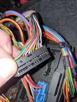
I've managed to get hold of a loom de pinned from a factory fitment cruise. This way I don't have to splice into the LCM wires and everything in installed as per the factory.

The wire to the ECU and ground are easy and sorted.

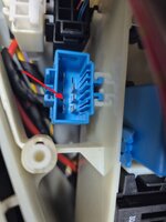
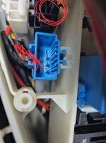
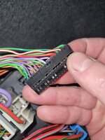
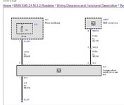
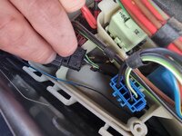
However, the wire to the fuse box is causing me some confusion. According to the wiring diagram, it should go to pin 7 of connector X11007 on the back of the fuse box and be powered by fuse 21.

However, this location is already taken on that connector block. I've searched through the wiring diagrams and come out with a pinout for X11007 but there are a number of discrepancies, like the wiring diagram is incorrect.

Does anyone know where the power supply wire actually goes on a Z4M?

For X11007 on the wiring diagram I've got:

X11007

Pin
1
2 VI/BR MFSW Fuse 13
3
4
5
6
7
8 VI/WS Run flat indicator supply
9
10
11 VI/WS passenger airbag deactivate (Fuse 28)
12 RT/GN electrochromatic mirror supply (Fuse 39)
13
14
15
16 GN/WS Electronic power steering (Fuse 22)
17
18
19
20
21
22
23 GN/BR OBD Socket (Fuse 9)
24
25
26 VI/WS seat occupancy (Fuse 28)
27 RT/WS crash safety module power supply (Fuse 28)
28
29
30
31
32 GN/WS heating and AC control power supply (Fuse 22)
 

Attachments

  • 20260301_120306.jpg
    20260301_120306.jpg
    544 KB · Views: 7
  • 20260301_120319.jpg
    20260301_120319.jpg
    481.5 KB · Views: 5
  • FB_IMG_1772205090584.jpg
    FB_IMG_1772205090584.jpg
    37.2 KB · Views: 6
  • 20260228_132800.jpg
    20260228_132800.jpg
    638.1 KB · Views: 8
According to the fuse guide (assuming M is the same) Fuse 21 is to the 'heated spray nozzles'.

Cruise control is Fuse 28.

But that doesn't equate to your pin out?
 
Okay that's helpful thanks, actually suggests that I need pin 7 of X11005.
Which also ties up with another diagram I had found from a different model of car.
X11012 is the switched supply from what I can tell on that diagram.

I will see if that pin is free and available.
Thank you.

According to the fuse diagram in the var it should be fuse 21, fuse 28 seems to be for pre FL cars.
You're right!
I was looking at the wrong label, sorry. Got you in the right area though.
Found it on NewTIS
 
Just check

When I fitted cruise to my m there was already a pin and wire in the correct location… which was unused

I spliced into this one and it worked

Have a search for srhutch original install thread I’ll see if I can find it
 
 
That's for the blue wire at the ECU end which I have sorted.
Most people splice into the power and ground at the LCM but I want to wire it back to the fuse box as per the factory install. Just about to check pin 7 of X11005 now...
 
Okay we have a winner, thank you to @enuff_zed . Pin 7 of connector X11005 is indeed vacant and a quick continuity test to fuse 21 confirms that it is powered from F21...

Thank you very much indeed.

No splicing needed anywhere for this retrofit.
 
Just to confirm my cruise control is installed and working, powered from pin 7 of X11005 and grounded in the ground block next to the fuse block as it would be from the factory.

For the Z4M, as has been explained before, the engine harness is already wired for cruise, but the connector that comes from the cabin is not populated with a wire. Therefore, for a factory install you just need to add the wire ans male pin, part (BMW Pin-Contact ELO-Power 2,8 x 0,63 0,35-0,5m² 61138373293) from the cruise stalk to connector X102 in the ECU box. Super simple and not a single wire spliced.

Picture shows the missing wire out of connector X102.
 

Attachments

  • 20260304_113618.jpg
    20260304_113618.jpg
    556.1 KB · Views: 9
010dom010.
I have been looking for this answer to finish my instal, thank you for posting, I can finish it off tomorrow. Cheers:)
 
Hi 010dom010.
I am back with a request for a little help if you can?

I have used the supplementary wiring loom to power the stalk splicing in to the lighting loom as directed in the BMW install manual. I have run the blue wire from from the stalk to the ECU Box. I took a look at connector X102 (the blue one in your picture) and Pin 7 which is empty, but which also does not have a pin so nothing to connect to ! Am I missing something ?
 

Attachments

  • 20260315_113213.jpg
    20260315_113213.jpg
    518.4 KB · Views: 6
So splice in to the Green and white wire.
Thanks for your help.
No, there is no wire to splice into on that side of the connector. You either need to install the wire from the cabin into the pin 4 of the black connector using the pin I mentioned.

Or splice into the blue wire running out of pin 4 on the female side of the black connector, that goes into the engine harness.
 
I've just re checked my photos. It is the black connector. Here is the wire to splice into.
 

Attachments

  • 20260315_113213.jpg
    20260315_113213.jpg
    537.1 KB · Views: 4
Back
Top Bottom