Nice job so far, the door lights are actually pretty good, not certain how difficult they would be to retro fit though

You are using an out of date browser. It may not display this or other websites correctly.
You should upgrade or use an alternative browser.
You should upgrade or use an alternative browser.
Footwell Lights Retrofit
- Thread starter Silverstar
- Start date
Ole gits rule said:Nice job so far, the door lights are actually pretty good, not certain how difficult they would be to retro fit though
Wiring wise I’ve figured it out - need separate wires from the passenger footwell to each door though. Then within the door really need the short loom with LED/connector to do it properly.
Not sure if that bit needs coding - I don’t think so though. The footwell and puddle lamps worked straight up - just populated the pin in the connector in the Footwell module and it all worked.
I only hooked up the footwell lights via connecting it to the dome light. I applaud you for doing the full retrofit and would be interested to see the write up!  Maybe another project for me for some time in the future, right now I need to finish up my audio install.
Maybe another project for me for some time in the future, right now I need to finish up my audio install. Silverstar said:I only hooked up the footwell lights via connecting it to the dome light. I applaud you for doing the full retrofit and would be interested to see the write up!
I’ve been taking lots of photos and started writing it up. Tomorrow hope to re-fit centre console and all should be ready (bar drivers door - wiring to the door connector is ready though, as is the short wiring loom - just need donor card
)I think the difference between wiring to pin in footwell module and to the interior lamp (I saw your post) is negligible. I wired it to the footwell module because a) it’s closer to the rest of the wiring, b) as it’s dedicated to footwell/ puddle lamps it should be rated accordingly and c) the behaviour MIGHT be different on this pin as the interior lamp generates its own on/off signal different to the footwell module.
Interestingly the two exterior door handle leds have separate wiring to two pins in the junction box, passenger footwell - to me that implies their behaviour will be subtly different too.
All said and done though, I suspect 99% of the operation is identical and I certainly didn’t have to do it this way


The exterior door handle lights come on with the key, the interior / puddle lights probably one come on when the door is opened - just a guess as I have not checked.
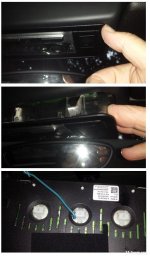
Remove the dome light assembly, get your finger nails in the gap and ease out.
It drops so far, then on the right side squeeze the lugs in and it drops out. Centre bulb holder remove and solder on wire.
Replace and see if attached light lights up, if not switch bulb holder around 180 degrees and try again.
I used signal from bulb to operate relay, so as not to put much load on it.
I will post picture later.
It drops so far, then on the right side squeeze the lugs in and it drops out. Centre bulb holder remove and solder on wire.
Replace and see if attached light lights up, if not switch bulb holder around 180 degrees and try again.
I used signal from bulb to operate relay, so as not to put much load on it.
I will post picture later.
flybobbie said:wire.jpg
Hi flybobbie just getting round to the soldering
Which bit did you solder to as it’s difficult to make out
Presume also earth is required?
If you look at flybobbie's pic where the wire is going to, you will see exposed terminals on the back of the holder. I soldered one wire to each side (top and bottom on flybobbie's photo) and ran the two wires down to the footwell to the new holder. I suppose you can also solder just one to positive terminal and take the earth from somewhere near the footwell area.
Silverstar said:If you look at flybobbie's pic where the wire is going to, you will see exposed terminals on the back of the holder. I soldered one wire to each side (top and bottom on flybobbie's photo) and ran the two wires down to the footwell to the new holder. I suppose you can also solder just one to positive terminal and take the earth from somewhere near the footwell area.
Thanks silverstar I will give it a go, didn’t want to mess up the unit
birdy_z4 said:Silverstar said:If you look at flybobbie's pic where the wire is going to, you will see exposed terminals on the back of the holder. I soldered one wire to each side (top and bottom on flybobbie's photo) and ran the two wires down to the footwell to the new holder. I suppose you can also solder just one to positive terminal and take the earth from somewhere near the footwell area.
Thanks silverstar I will give it a go, didn’t want to mess up the unit
You are only soldering to the bulb holder so you can't really mess it up and anytime you want to return it to stock it's just a case of buying a new bulb holder which shouldn't be expensive.
Unscrew the bulb holder and solder on long wire to metal terminal.
Screw back in with wire to left which is positive.
Then i ran the wire to a relay and suitable negative.
Relay then used to power the footwell, door, sill lights.
Also some white leds to light up behind seats.
Screw back in with wire to left which is positive.
Then i ran the wire to a relay and suitable negative.
Relay then used to power the footwell, door, sill lights.
Also some white leds to light up behind seats.