Double Din Fasica Progress [UPDATED: 1st September 2017]

Roundozo said:
I also think no branding. If people want to wrap it, it'll be really difficult with the Z4 logo. You could always buy a boot set and stick it on afterwards if you want it.

Agreed. Plain is the way. I personally like to keep things simple.
 
Yup all agreed, no branding as you're right wrapping would be a nightmare!

Thanks for the input all :)
 
This tech is way over my head but I'm seriously loving this and would be very interested in the finished article :thumbsup:
 
Leesfarm07 said:
This tech is way over my head but I'm seriously loving this and would be very interested in the finished article :thumbsup:

Thanks :D

I've decided to write a "project z4" post that will cover all the actual work involved as well as all the other bits I'll be doing. I will keep this thread updated with results of the fascia too though :)
 
No branding imo, enough logos already on the steering, the gearstick all the wheels boot/bonnet etc
 
Ant said:
No branding imo, enough logos already on the steering, the gearstick all the wheels boot/bonnet etc

Yeah I've deleted the branding now.

Another update for all... I was debating on whether or not to try and match the curvature of the frame... I've managed it and personally I think it looks good. The only thing is it makes the piece bendy and thin in the middle so would have to handle with a little care whilst fitting / wrapping.

Let me know thoughts.

IMG_1224.JPGimage.jpg
 
Matching the curve looks good. Now that you've got the angle for the front, could you not add more to the rear of the curve to add strength?
 
Roundozo said:
Matching the curve looks good. Now that you've got the angle for the front, could you not add more to the rear of the curve to add strength?

There's only realistically 3mm depth to play with which makes it tricky. It shouldn't be too bad as once it's screwed to the mount it won't be so weak and you wouldn't be able to just push it back and break it easy so tough wood it'd be fine :)
 
tbh it depends how the doubledin is going sit inside it, like if you can see the sides/metal because of the curve then you'd be better to keep it like a standard fascia i guess

like how does it look with the unit slid in? eg this picture, they fill it out to cover the sides of the stereo

12032009029.jpg
 
Ant said:
tbh it depends how the doubledin is going sit inside it, like if you can see the sides/metal because of the curve then you'd be better to keep it like a standard fascia i guess

like how does it look with the unit slid in? eg this picture, they fill it out to cover the sides of the stereo

12032009029.jpg

Yeah I know what you mean... I will have to experiment as I get closer to the final result. I've been trying a few test prints and made some changes to the design again. I don't think it needs a full cage so to speak... just deep enough sides with cutouts so the the stereos cage tabs can be folded stopping the cage from being able to be pulled forward. Also added some triangular supports for the frame edge.

Screen Shot 2017-06-18 at 22.45.53.png
Screen Shot 2017-06-18 at 22.46.01.png
 
its great to watch the R&D progress. doing a fine job with the latest design updates mate.
How they've managed the fascia curvature against the flat head unit in the above single DIN example is actually really neat. interested to see how you deal with that with this design.
 
cyrilsneer88 said:
its great to watch the R&D progress. doing a fine job with the latest design updates mate.
How they've managed the fascia curvature against the flat head unit in the above single DIN example is actually really neat. interested to see how you deal with that with this design.

Haha thanks. I've since removed the curvature I had put in, mainly due to the limitations of my printer. I'm working out some more bits today including how I might be able to extend the vent round to each side of the stereo etc. Challenging for sure given my lack of skills lol
 
This is really coming on well, great work and I'm looking forward to see the fully finished article.

I've got a pioneer head unit sitting gathering dust....shame :D
 
Killiestu said:
This is really coming on well, great work and I'm looking forward to see the fully finished article.

I've got a pioneer head unit sitting gathering dust....shame :D

Thanks :) I'll try & get an update posted tomorrow afternoon. I made a boo boo of test fitting the design in the fascia, I test fitted the cage in the design - but never did both at the same time until the other day and realised I had a slight design flaw ha!

I'll post the update tomorrow and will hopefully make sense with pics etc
 
IAmOrion said:
Killiestu said:
This is really coming on well, great work and I'm looking forward to see the fully finished article.

I've got a pioneer head unit sitting gathering dust....shame :D

Thanks :) I'll try & get an update posted tomorrow afternoon. I made a boo boo of test fitting the design in the fascia, I test fitted the cage in the design - but never did both at the same time until the other day and realised I had a slight design flaw ha!

I'll post the update tomorrow and will hopefully make sense with pics etc

Suppose even the best design's need to go through the whole process before there done.

And at least go did something about it, I'm good with spanner but completely usless with computers, the whole design would live in my head forever! You've thought it through and actually made it ! :thumbsup: nice one.
 
Killiestu said:
Suppose even the best design's need to go through the whole process before there done.
And at least go did something about it, I'm good with spanner but completely usless with computers, the whole design would live in my head forever! You've thought it through and actually made it ! :thumbsup: nice one.

Ha very true! :)

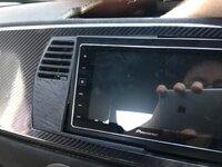
Another short update, after actually fitting the fascia I had printed, and putting my pioneer head unit into place - I realised I had a fundamental flaw in the design. This is mainly due to fact that the Double Din unit can NOT match the angle of the trim area. As you may have read in a previous post, I had added a curve to the fascia but due to printer limitations in terms of quality of the print, I then removed the curve and kept the "flat" face.

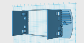
After trying a fit with the cage in place AND the head unit itself, I realised the cage walls needed to be at an angle
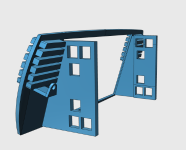
Screen Shot 2017-06-25 at 18.05.43.png

Also, due to printer constraints and the way in which FDM printing occurs, there was very little strength where the edges of the cage met the front of the fascia. After trying numerous print orientations and settings to increase the strength and some discussion in a 3D Printing group, I decided to print the walls separately and use JB Plastic Weld Epoxy to affix the wall/edges to the fascia front.
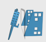
Screen Shot 2017-06-25 at 18.06.07.png

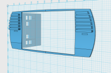
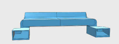
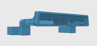
There was also the fact of working out a venting system ... this is still very much a work in progress, but the current stage looks like this:
Screen Shot 2017-06-25 at 18.09.50.png
Screen Shot 2017-06-25 at 18.09.59.png

This too will be in sections that would need to be epoxy'd together... and I would also use some silicone at the join lines to help make it air tight.

As always, this is still a WIP - but I believe my fascia is almost complete
nUMZsqQ.jpg

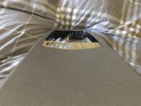
In my case, there was 2 options, have the bottom flush at the front, and the top protruding - and then fashion some kind of top cover, OR as in the pic, have the top flush, and the bottom is set back and I will at some point fashion something to cover the gaps left (please note, that in the pic you can see it is merely propped up in place, it would infact sit a little further back and "beyond" the fascia a fraction). The stereo is too large to match the angle of the fascia... I am currently printing off my venting design thus far.. I will update again once it's finished printing and I can get an idea of the next step.
 

Attachments

  • Screen Shot 2017-06-25 at 18.09.59.png
    Screen Shot 2017-06-25 at 18.09.59.png
    38.8 KB · Views: 2,393
  • Screen Shot 2017-06-25 at 18.09.50.png
    Screen Shot 2017-06-25 at 18.09.50.png
    26.2 KB · Views: 2,393
  • Screen Shot 2017-06-25 at 18.06.07.png
    Screen Shot 2017-06-25 at 18.06.07.png
    106.6 KB · Views: 2,393
  • Screen Shot 2017-06-25 at 18.05.43.png
    Screen Shot 2017-06-25 at 18.05.43.png
    105.6 KB · Views: 2,393
Hi, does it sit like that because the 2 din stereo hits the bottom? if so, as you have already cut out the air vents behind and it wont be standard any more, why not make the fascia larger and increase the hole in the dash panel a little at the top.
Or is that not possible.
Then wrap the hole trim panel as one to hide the joints.
Just a suggestion,
 
A top cover might not be a bad idea!

Might help with the glare the screen will catch at the angle, loving the progress
You can buy high grip/strength adhesive that will have enough "flex" to allow the natural vibrations of the car so having to print it in 3 or more sections shouldn't be a problem at all.

Your clearing the design hurdles no bother bud keep it up and you'll be selling these in no time.
 
Dr-Jon said:
Hi, does it sit like that because the 2 din stereo hits the bottom? if so, as you have already cut out the air vents behind and it wont be standard any more, why not make the fascia larger and increase the hole in the dash panel a little at the top.
Or is that not possible.
Then wrap the hole trim panel as one to hide the joints.
Just a suggestion,

Yes, the problem, is that if you cut out that bottom, then there's nothing what so ever to support the unit and I don't think you could realistically make something to replace it that would be able to maintain the desired strength (Also, that part forms part of a larger supporting frame behind the dash. Also, whilst I'm happy chopping bits that are hidden away such as the vent (which was easy) I don't fancy messing with the metal trim that is visible if that makes sense. My fabrication skills aren't the best haha. Maybe someone with better 3d design skills could pick up where I leave off... I don't get on with fusion360 so am also limited by the software I use (123D Design) ... but also, I'm happy enough with it set back a fraction - it works for me, but I will supply the finished files so others can edit and amend etc if they want to build on it.

And yes, the idea behind the main fascia panel IS that it would be epoxied together, and then wrapped as one piece.

Killiestu said:
A top cover might not be a bad idea!

Might help with the glare the screen will catch at the angle, loving the progress
You can buy high grip/strength adhesive that will have enough "flex" to allow the natural vibrations of the car so having to print it in 3 or more sections shouldn't be a problem at all.

Your clearing the design hurdles no bother bud keep it up and you'll be selling these in no time.

Yeah a slightly flexible epoxy would be the most ideal as it allows for some very slight movement. The Pioneer SPH-DA120 is pretty good for glare - however for my particular case I actually like it set back a fraction... all to do with interaction with the unit, as daft as it sounds, If there's some random need to do something whilst moving or quickly at red lights (tut tut whilst moving I know!) I kinda like having a very small ridge on which I could rest my palm edge on as I rapidly finger stab the screen haha
 
Back
Top Bottom