Add-a-Fuse help please!

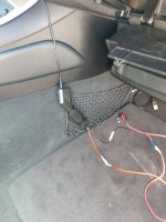
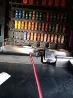
Hey all, I'm new here but I was hoping for a quick assistance to the issue I'm currently having of adding a gps module to my Z4. So I have bought a female connector for the 12v accessory plus in the GPS came with. I've connected the GPS 12v male charger to the female connector and run a wire to a crimped add-a-fuse device with a 10 amp fuse on it. The ground wire is running to a screw just below the glove box which is helping to secure the glove box on the dash. I've tried to power this on a number of ways now:
1. Add a fuse device with 10 amp fuse into an empty fuse slot (F2). Nothing.
2. Add a fuse device connected to an existing 10 amp fuse F6 (with my added on fuse in the second slot). Nothing.
3. I have tested the GPS 12v male connector into the cigarette lighter and it turns right on. So it seems to be operating just fine.

Each time in each of these configurations I have turned the key all the way over and nothing happens with the GPS. I'm lost here!
Could it be a bad ground on that screw? I have tried flipping the way I put the fuses in all different orientations to no success as well. (no blown fuses either).

Gods, help me please! :headbang:
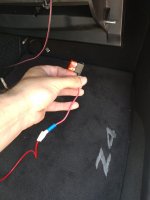


addafuse.jpg

12v wiring.jpg

fusebox.jpg
 
Did you check your earth screw and wire for continuity back to a good earth somewhere on the car? If not, it's a bit of a guessing game at the moment.
 
Success, was able to test an actual grounded screw and it works just fine. The problem now is that the screw I tested was attached to the passenger side center console and it would be ugly as hell running that wire. I need to find a good ground somewhere to solder or attach it to that I can keep out of sight. The good news is that the circuit works fine! Now to just keep it looking nice.
 
Those screws don't earth as they only secure the bottom on the glove box to the plastic trim. Remove the glovebox and there are two screws either side that go into the dash crossmember and are therefore earthed.

Mike
 
Can I ask how you've joined your wires together? I get the feeling you're learning on the job a bit with this installation, which is great (we all have to learn these things). Ideally, your joints would be soldered and then covered over with heatshrink. If you don't want to use heatshrink, the next best thing would be insulation tape. Masking tape isn't very sticky and isn't very durable, leaving it likely to rub through in time. This means your wires might start shorting out, causing a fire hazard and unreliable operation. If you don't want to solder the joints, the next best thing would be crimped bullet or spade terminals.

Your earth point would ideally have a ring terminal crimped on which would then make a good contact under the head of the screw you chose to use, rather than having some twisted wires squashed in as you tighten the screw. The work I've listed above would only add about 10 minutes to your job but would make it a reliable and durable job, plus it would look good and professional. Advice you can either heed or ignore, of course - it's your car after all :)
 
An alternative to solder, and the method I've always been taught is actually preferable is crimping and heat shrink. Solder can have an effect on the resistance of the wire or something, whereas crimping is purely securing the two wire pieces together via mechanical means.
 
The easiest method of soldering two wires together with a degree of integrity is to use solder sleeves like: https://www.amazon.co.uk/Connector-...qid=1529926358&sr=8-1&keywords=solder+sleeves.

These contain a controlled amount of low melting point solder in a shrink sleeve. The shrink sleeve also has glue rings for sealing/additional strength. simply select right size, bare 6mm of wire for each wire. Butt together inside shrink sleeve overlapping the bare copper and heat up with a heatgun.
 
mjennings23 said:
An alternative to solder, and the method I've always been taught is actually preferable is crimping and heat shrink. Solder can have an effect on the resistance of the wire or something, whereas crimping is purely securing the two wire pieces together via mechanical means.
Also solder can corrode in time.
 
Hey all, the tape in the picture was temporary for testing purposes, all wire joints have been crimped together in a much more permanent arrangement along with a soldered on ring for the grounding to the screw. :D
 
Ducklakeview said:
Those screws don't earth as they only secure the bottom on the glove box to the plastic trim. Remove the glovebox and there are two screws either side that go into the dash crossmember and are therefore earthed.

Hmmm, I wonder if that is different on some models as I picked up my earth on that screw no problem. It actually fixes the plastic trim into a steel bar which you can clearly see in the pics above. You can even see welds on it.
 
Magicarcher said:
The easiest method of soldering two wires together with a degree of integrity is to use solder sleeves like: https://www.amazon.co.uk/Connector-Conn ... er+sleeves.

These contain a controlled amount of low melting point solder in a shrink sleeve. The shrink sleeve also has glue rings for sealing/additional strength. simply select right size, bare 6mm of wire for each wire. Butt together inside shrink sleeve overlapping the bare copper and heat up with a heatgun.

As an electronics engineer I suspect a lot of the reviews on these could be fake. Given that solder needs to be at least 190'C to melt and probably more like 300'C to heat the copper in the wire for it to flow properly, I'd expect the heatshrink to split open long before the solder connection is made reliably. Then you have the danger of the heatgun melting everything else in the vicinity like trim etc.
 
ph001 said:
Magicarcher said:
The easiest method of soldering two wires together with a degree of integrity is to use solder sleeves like: https://www.amazon.co.uk/Connector-Conn ... er+sleeves.

These contain a controlled amount of low melting point solder in a shrink sleeve. The shrink sleeve also has glue rings for sealing/additional strength. simply select right size, bare 6mm of wire for each wire. Butt together inside shrink sleeve overlapping the bare copper and heat up with a heatgun.

As an electronics engineer I suspect a lot of the reviews on these could be fake. Given that solder needs to be at least 190'C to melt and probably more like 300'C to heat the copper in the wire for it to flow properly, I'd expect the heatshrink to split open long before the solder connection is made reliably. Then you have the danger of the heatgun melting everything else in the vicinity like trim etc.

Also an electronics engineer used them for years as a production solution for screened cable termination on gas turbines used for marine propulsion albeit they were Raychem devices rather than far eastern copies. Have used them occasionally for in-situe automotive repairs where I can't get in with proper crimp tools and always been happy with them. I tend to force the two butted wires into one another rather than lie alongside each other so individual wires are in contact with each other, you can actually see the solder melt and flow between the wires. They are less risky than soldering individual wires together in untrained hands. Personally if it were me I would use a two way inline connector, but to go a good job you need good crimp tools, knowledge how to use them and a good idea of what is and isn't a good crimp. Judging by the picture of the "earthing" method shown in the picture on the first post, inline connectors are not likely to be appropriate.

I share your suspicion of fake reviews, my belief is that that is a common problem.
 
ph001 said:
Ducklakeview said:
Those screws don't earth as they only secure the bottom on the glove box to the plastic trim. Remove the glovebox and there are two screws either side that go into the dash crossmember and are therefore earthed.

Hmmm, I wonder if that is different on some models as I picked up my earth on that screw no problem. It actually fixes the plastic trim into a steel bar which you can clearly see in the pics above. You can even see welds on it.

The screws fixing the bottom of the glovebox go into metal clips, which are fixed to the trim panel only. The two screws either side go into the steel crossmember.

Mike
 
I have some photos on my thread a while back (https://z4-forum.com/forum/viewtopic.php?p=1365811#p1365811) I put a powered USB socket in the glove box for charging my phone etc. Just to echo previous comments, remove the glove box to get to a suitable ground screw, and definitely soldering connections is the best option.
 
Back
Top Bottom