 Scottish Borders
Ah..I see your problem ref Indys that will touch the roof..really admire your patience and tenacity!Boise, Idaho, USA.
You are using an out of date browser. It may not display this or other websites correctly.
You should upgrade or use an alternative browser.
You should upgrade or use an alternative browser.
A670 code in CTM after Convertible top wiring harness replaced
- Thread starter accts4mjs
- Start date
These two buttons switch GROUND to the CTM. You can't measure any voltage on these two wires.I hooked up my foxwell to watch the live data and it does not register when I press either button. Have you run into the top up/down buttons not working before?
Try to check it with a beeper on your voltmeter on the two pins at the CTM.
I assume they never are source of an issue.
Last edited:
 Boise Idaho
@RobbiZ4 - Great news (with one small problem left)! I bought the 540320 tool to unlock the rear roof and it worked great. Super easy to use. If anyone needs it you can purchase it from Turner Motorsports: https://www.turnermotorsport.com/p-31655963-tools/
I then took a 12V battery and touched the two wires to the large lines on the roof cowl locking motor and it unlocked the front cowl. With the pneumatic pump valves open again I was able to manually lift the two roof sections up and take the tops off to get to the wires again.
After getting the roof open again, I undid all of the connections on my wires and soldered them up with shrink tubing that had built in adhesive (great stuff for keeping moisture out). All of the errors cleared up. I then removed the kinetic boxes in the trunk (boot) and replaced the two switches (one on each side) and soldered those lines back in too. I then soldered the final lines to fresh connections into the 26 pin connector for the CTM.
Unfortunately the open and close buttons in the center console still don't do anything. So, following your recommendations, I put a back pin into pins 13 and 14 on the 41 pin connector (which are the ground lines from the open and close buttons). I tried to see if there was any voltage being registered with the car on but 0V DC was all I got (I thought maybe it would be 12V and then 0V when triggered). I also tried to measure Ohms and it stayed Open (Infinity) no matter what I did with the buttons. Finally, I ran the line from each pin (one at a time) to ground on the car and as soon as I did that the roof started moving. I was able to get it to close fully and the red flashing light went off and I could move the windows up and down. I then got it to go fully open (with roof package in the boot) and windows also operated when it was done with no lights flashing. I did this 3 times in a row and it worked perfectly each time.
So...I'm super close. I just don't understand why the buttons aren't triggering the Top to go up or down.
I'd love any suggestions you might have for next steps. My thinking is to pop the center console open and pull the button switches out and see if I get a closed circuit between the button and the 41 pin lines on 13&14 in the CTM. If I don't then there's a breakdown in wiring between the center console and the CTM.
One other oddity is somewhere along the way of fixing the roof my passenger side seat (right side of the car if facing the engine from the seat), I started getting errors related to the passenger restraint safety system. Is that somehow related to the open/close buttons?
Thanks for all your help! I'm so close to being done!!!
Great success!
I don't have any idea, why these wires should fail.
In INPA/ISTA (sensors), you can follow up the button's state without disassembling anything.
Both buttons are directly wired to the CTM, grey/blue for Open, grey/black for CLOSE.
As a 2nd step, you can connect each console's pin manually to ground to check the CTM's reaction on it.
Finally, you can measure continuity of these two buttons from the console's connector up to the two pins on the CTM.
Internal view
and
 www.zroadster.com
HowTo:
I don't have any idea, why these wires should fail.
In INPA/ISTA (sensors), you can follow up the button's state without disassembling anything.
Both buttons are directly wired to the CTM, grey/blue for Open, grey/black for CLOSE.
As a 2nd step, you can connect each console's pin manually to ground to check the CTM's reaction on it.
Finally, you can measure continuity of these two buttons from the console's connector up to the two pins on the CTM.
Internal view
and
⌛ Z4 E89 - Dachbedienung über Tasten in Mittelkonsole ausgefallen - gelöst ☕
Seit gestern funktionieren die beiden Tasten in der Mittelkonsole zum Öffnen und Schließen des Daches nicht mehr. :thumbsdown: Die anderen 3 Tasten in derselben Leiste (Sitzheizungen und PDC) funktionieren einwandfrei. Es hat seit dem letzten Funktionieren keinerlei Störung oder besondere...
HowTo:
Last edited:
I'm not sure if that is an easy job, as the contacts are on a PCB like a remote control unit. Maybe an "interpreter" is working in the background.'ll open up the console and pull the switches and see if I can read them switching ...

Last edited:


Last edited:
@RobbiZ4 I pulled that control panel out last night. You're right, it's definitely a PCB that is logic based and not analogue voltage up/down based. My research leads me to believe it might be the JBE I need to look at next.
I spent some time last night loading information to chatGPT to have it scan sections of the full BMW Z4 e89 service manual (the PDF I have is 6985 pages long). I gave it sections on accessories and body, accessories and wiring diagrams, and general info and diagnostics. One of the pages shows the 41 pin connector pinout from the CTM and a line that goes to a mysterious dotted line "center console switch center". GPT confirms that there is a logic module in between the switches and the CTM as the switches do not draw down ground directly to activate the CTM on pins 13 or 14 (open or close). Sounds like either the JBE does it or there's another module between the switches and the JBE that tells the JBE to do it.
I've attached the 18 step diagnostic plan that GPT put together for me. It may or may not work but it's more than what I had last night. Next I'll be trying to find more information on the JBE, how it works, and any pinout information for it. If anyone has tips or links on that, that would be super helpful!
Attachments
It's nonsense as often. Follow the basics, read circuit plans.
Update:
It may depend on your engine!
- With Start/Stop (4 cylinders 18i,20i,28i)
For these models the documentation is contradictory!- For the two roof buttons, the same cicuit plan is presented as for the 6-cylinder models.
.jpg")
- For the Start/Stop button there is a completely different cicuit plan available!
The center console switch unit got connected against the climate control unit and is working over the CAN bus!
I assume, that the following is NOT correct! It looks like it was mistakenly taken from the E88 1 Series convertible.
- For the two roof buttons, the same cicuit plan is presented as for the 6-cylinder models.
- Without Start/Stop (6 cylinders 23i,30i,35i/s)
As said, 2 wires directly to the 41 pole plug of the CTM.
Put ground on the 2 pins of the disconnected 20-pole plug to measure continuity and test the roofs function.
Last edited:

And I finally see the gray/blue and gray/black wires. 
And here’s the labeled PIN numbers on the connector (mine is 20 pins).

Pins 2&3 correspond to the diagram and match the wire colors. I’m about to test continuity between these pins and the pins on the 41 pin connector of the CTM. If there’s continuity then I’ll try a direct ground from the switch after reattaching the battery and turning the car on. If that works I guess that means I have a bad switch PCB and will need a new one?
And here’s the labeled PIN numbers on the connector (mine is 20 pins).
Pins 2&3 correspond to the diagram and match the wire colors. I’m about to test continuity between these pins and the pins on the 41 pin connector of the CTM. If there’s continuity then I’ll try a direct ground from the switch after reattaching the battery and turning the car on. If that works I guess that means I have a bad switch PCB and will need a new one?
Correct, it's a 20-pole connector.
Another question:
What about your seat heating buttons? Do they work? If not, a fuse could have been blown to support power supply of this module.
Assumption: pin 14 = GND, 17 = VCC from fuse 05 (10A).
Connect it with the 20-pin connector and measure GND from the two buttons (pins 2+3) with a beeper connected to VCC or a multimeter connected to GND.

It seems to be located on top of the foot rest. ON RHD cars probably on the right.

Another question:
What about your seat heating buttons? Do they work? If not, a fuse could have been blown to support power supply of this module.
Assumption: pin 14 = GND, 17 = VCC from fuse 05 (10A).
Another idea to test your module:Problem identified. There is no continuity between pins 2/3 and 13/14. Now what do I do?
Connect it with the 20-pin connector and measure GND from the two buttons (pins 2+3) with a beeper connected to VCC or a multimeter connected to GND.
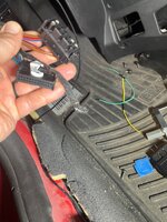
Interesting in deed. On the above plan you can see a connector between the 20-pole connector and the CTM: X9331. That could be another checkpoint towards the CTM. Check it for corrosion, as I saw already water even inside the JunctionBox next to the fuse panel.And a better question: how on earth could that have happened??
It seems to be located on top of the foot rest. ON RHD cars probably on the right.
Last edited:
Thanks Robbi! You answered my next question which was, where is the connector at. Maybe I disconnected it accidentally  . My OBDII connector mount is broken and I couldn’t press the reader on all the way and it shorted out my reader. So I took the foot panel off to get to the OBDII connector. I’m at church now but will check later tonight. This would be awesome if it’s just unplugged and I can plug it back in.
. My OBDII connector mount is broken and I couldn’t press the reader on all the way and it shorted out my reader. So I took the foot panel off to get to the OBDII connector. I’m at church now but will check later tonight. This would be awesome if it’s just unplugged and I can plug it back in.NewTISHow do you get these amazing photos?

Sooooo…turns out if you unplug the main connector it kind of won’t work. 
Robbi, you are the man!! Wish I could take you out for lunch or something! I plugged the cables back in and cleared all the codes and the top goes up and down again. I am back in business!!! Now to put all the liners back together. But that’s wayyy easier than anything else I’ve done at this point.
Seriously, I couldn’t have done it without your help!! Thank you, thank you, thank you!!
Attachments
Wow, what a great news from Idaho!!!
And a very long journey over 3.5 months!
July '25
September '25
End of October '25
Congratulations on the IMHO worldwide first replacement of the hydraulic wiring harness with a homemade one.
Btw, do you have some pictures of your rebuilt harness for future reference, when BMW will not be able to deliver replacements any more?
Last edited: