Hydraulic Steering Conversion (for M54 engines)

PhilMGCollins

Member
UK, Northamptonshire
I'm making this post as a supplemental guide off the back of the great information provided by two other member's threads on this conversion (credit also to the contributing members who continued those threads with more information - too many of you to name!):

(M54 specific conversion) @raymond.harper - https://z4-forum.com/forum/viewtopic.php?t=92858
(N52 specific conversion) @Hydro_Z4 - https://z4-forum.com/forum/viewtopic.php?t=118282

So hopefully this helps clarify a few parts of the installation/conversion. I don't want to leech the credit off them, so this will consist of my own photos with explanation, with links to the above two threads as necessary - but feel free to ask anything if it's not clear! I can't promise I've covered off everything so if you feel something is missing, you just may be correct haha.

The below parts list shows what parts are required, and this is where for some parts I'd encourage finding a fellow BMW owner who is breaking an E46 3 series, since some of the parts are discontinued by BMW or they have long lead times on delivery. Also, in lieu of locating the part numbers, please refer to Hydro_Z4's thread as it contains a comprehensive parts list, where some parts are interchangeable between M54 & N52 engines.

--------------------------------------------------------------------------------------------------------
Power Steering Reservoir & Hoses:

A) Power Steering Fluid Reservoir: 32416851217
B) Reservoir Mounting Bracket: 32411092940
C) Fluid Cooler Loop: 17111436262
D) Reservoir to Pump Hose: 32411095526
E) Reservoir to Cooler Loop Hose: Can't locate specific part number - see Hydro_Z4's thread linked above. Part 11 in image on page 1 under "Hoses (LHD)" or Part 14 on page 1 under "Hoses (RHD)"

((https://www.lllparts.co.uk/product/32411092940/bracket-oil-carrier) Reservoir diagram for further information
--------------------------------------------------------------------------------------------------------
Power Steering Pump:

A) LF-20 Power Steering Pump: 32416760036 (lots of different part numbers for this, 32416760034 also appears correct and I believe it is the former pump revision, before being replaced by the ..036 designation)
B) LF-20 Power Steering Pump Pulley: 32421740858
C) LF-20 Power Steering Pump Pulley Bolts: 07119915067 or 07119905527
D) LF-20 Forward Mounting Bracket: 32421740780 (find a breaker - on back order from BMW with no ETA when I tried ordering on 30/01/2025)
E) LF-20 Rear Mounting Bracket: 32421438695 (find a breaker - discontinued by BMW)
F) LF-20 Fwd/Rear Mounting Bracket Bolts (3 different ones needed): 1: 07119905403. 2: 07119900265. 3: 07119905529

With luck from a breaker, you can find an entire pump assembly, including the forward & rear brackets, pulley and all necessary bolts. I also tested fitment with an LF-30 pump (32411094965) used in later BMW 3 series models and it does fit when mounted using the above LF-20 forward mounting bracket, however the LF-20 rear mounting bracket will not fit between the pump & engine block mounting location properly. Also it appears that the offset of the LF-30 pump pulley mounting face means it does not line up with the rest of the Drive Belt pulleys; thus, I've concluded the LF-30 pump cannot work on the M54 engine block and will only work on the N52 engine block. This is also the reverse, so an LF-20 pump will not work on an N52 block.

((https://www.lllparts.co.uk/product/32421438695/bmw-32421438695-rear-vane-pump-bracket) or (https://www.lllparts.co.uk/product/32411094965) These are diagrams of the entire LF-20 pump assembly. Match up part numbers with diagram in your own time :) )
--------------------------------------------------------------------------------------------------------
Steering Intermediate (Lower) Shaft Assembly, Steering Rack & Lines:

Hydro_Z4's thread details more about which racks/shafts (insert joke here) are available for the conversion, my kit came with the below:

A) Steering Rack (Purple Tag E46 rack): 6755067
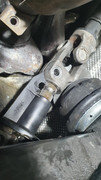
B) Z4M Intermediate Shaft: 32307836811 (It's here worth noting that a commonplace E46 intermediate shaft will not fit onto the Z4's upper steering column assembly so this Z4M part is required as it does fit between an E46 steering rack and Z4 (non-M) upper steering column assembly. This Z4M rack new is very expensive and may also not be available, so I advise to find either a breaker of a Z4M who will sell you this part, or see further in Hydro_Z4's thread about fabricating your own intermediate shaft. Link to new Z4M intermediate shaft: https://tinyurl.com/5crvvnea)
C) HP Line from Pump to Steering Rack: 32416774215 (Mentioned in Hydro_Z4's thread that this is LF-30 specific, however in my findings, the HP line in my kit fits both the LF-20 & LF-30 pumps, so I conclude that the connection type is the same and therefore this part is interchangeable - this with the caveat that my kit did have a couple self-made parts so this could be one of them, but since the thread pitch etc is the same between my LF-20 & LF-30 pumps, I assume the fact it may or may not be a self-made part is irrelevant. Open to correction here :) )
D) Hose from Steering Rack to Fluid Cooler Loop: 32416774214

((https://www.lllparts.co.uk/product/32416774214/bmw-32416774214-return-pipe) There are further ancillaries like fluid line bolts etc, all part numbers can be found on the linked parts page - this is for RHD vehicles)
--------------------------------------------------------------------------------------------------------
I believe the above contains all necessary parts to carry out this conversion, minus things like:
A) Tie rod assemblies, which for my build at least, I just swapped over between my Z4's stock steering rack and the E46 purple tag steering rack. I then used thick cable ties to fasten the tie rod boots over the steering rack and also to the outer track rod assembly.
B) There are also some bolts which you are advised to buy new for the installation, such as the E10 torx bolts connecting the Intermediate (Lower) Shaft assembly to both the steering rack and the upper steering column assembly - here I am just going to reuse these and apply a blue threadlock.
C) Hose clamps are required for some of the connections (such as the hose from the reservoir to the power steering pump). I bought a small assorted box of hose clamps and used whichever ones fit. From scouring the web, I found the torque specs for these clamps to be only 5.5nm so the chance of a hose clamp not seating properly and then failing are low I feel.

I will continue this in a further post below just for clarity/distinction.
 
** I forgot to mention a new part you'll need which is a new drive belt, since the new power steering pump pulley is larger than the idler puller that you remove in its place, so you'll need a longer drive belt to match. 6PK drive belt part number: 6PK1538 **

Here is an overview image of all the parts I received in my kit and how they connect:
20250116-113930.jpg

Note that this contains an LF-30 pump and relevant lines & reservoir brackets (including a self-made bracket by the previous owner) to fit an N52 engine however the premise of how the parts connect on an M54 are the same. I had to source the parts as listed in the first part of this guide, so following images will show the relevant M54 parts and installation - enjoy the colourful guide scribbles!

Starting with the easiest part of the installation, the power steering fluid reservoir and bracket, which mounts onto the Oil Filter Housing (this is the factory location on an M54 engine block). It sits above the alternator, and is mounted using two bolts as can be seen in the image. The wiring present on your engine will need maneuvering into a suitable location as the reservoir bracket interferes with this. The hoses to the pump & cooler are present in this photo, but you don't need to mount these just yet if you don't want.
20250225-130542.jpg

I would mention here that I removed the fan from the radiator pack for better ease of access (as I was also fitting other new parts to my car at the same time as doing this steering conversion). I didn't take photos of this but you'll need to remove the radiator pack cover which is held on by various plastic screws which you'll need to remove carefully so as to not strip them. Once removed, it will reveal the radiator pack. There is one screw on the offside which connects the fan housing to the radiator pack, and then there is one push clip fastener on the nearside, near the coolant expansion tank filler point. Remove these two fasteners and then unclip the wiring connections - one on each side of the fan. They're easy to identify. The fan can then be lifted straight up and out of the engine bay; you'll now have much better visibility of the front of the engine which is good for this conversion and other work.

Next step is to create space for the power steering pump. This is currently taken by an idler pulley just below the alternator and is best removed from the underside of the car (in this photo the undertray is removed for ease of access). It is highlighted by the obvious (hopefully) blue arrow. Release tension on the drive belt first by fitting a 16mm socket to the tensioner pulley bolt (the tensioner pulley is mounted to the upper left of the indicated idler pulley, and the 16mm bolt you are to locate sits just to the left of this tensioner pulley - not seen in photo but hopefully other forum threads help you here)
20250212-175219.jpg
I didn't photograph this but in order to fully remove the drive belt, you'll also need to remove the auxiliary belt which runs the A/C compressor. This is done in the same fashion, identify the tensioner pulley and relieve tension on the belt in order to remove it. This will then allow you to remove the drive belt from the assembly, as it is kept behind the aux belt on the crankshaft pulley/harmonic balancer.

The pulley is held on by two bolts (left loose in the photo below and which can be reused when fitting the power steering pump) as can be seen below, both 13mm hex bolts. One is removed from the front of the engine, the other is best accessed from behind the pulley, from the nearside of the car, above the outer track rod assembly:
20250212-175659.jpg

Now you're ready to mount the power steering pump. It uses those same two bolt locations as the idler pulley, plus a third bolt which connects the pump directly to the engine block. Here's a view of the rear of an LF-20 power steering pump and rear mounting bracket - note that the pump pulley is not fitted yet.
20250212-180223.jpg
ChrisFix on YouTube has a video on how to fit a power steering pump and it just so happens to be on an M54, but some of the brackets are different: https://www.youtube.com/watch?v=04iDF3I6dTo&t=1217s

When fitting the pulley, if you've acquired the parts separately from the list at the start of this post, you'll just need to bolt the pulley to the pump which is fairly straightforward. I recommend cleaning off the pulley mounting surface on the pump and applying some anti-seize, as the pulley fits very tightly onto the pump - it's best pressed on gently (as it's usually a plastic pulley) by hand to start and then fastened on by the pulley mounting bolts incrementally in a circular manner to achieve an even pressure.
20250212-210917.jpg

Hooray the pulley, pump & reservoir are on. Next I did the steering rack, so feel free to do the same.. or don't! Before you start this, make sure you lock your steering column in the straight-ahead position and remove the key to avoid accidental movements to it. If not done correctly, you may cause damage to internals of the steering column. This is easy to avoid by locking the steering, so don't miss this step.

You first need to remove the aluminium reinforcement place from the subframe/chassis - again, I hope you'll find the forum useful here for how to remove this, but simply there are around 8 big 19mm bolts I believe which connect at various obvious locations. With that out of the way, there are two bolts (highlighted in blue circles) either 15mm or 16mm I can't remember, which connect the steering rack between the subframe and fasten using nuts on top of the subframe (highlighted where the blue horizontal lines are).
20250225-132716.jpg
You'll need the appropriate socket and spanner to loosen them. Access is fairly easy here - the photo above shows the hydraulic rack fitted, but the mounting is the same. With both bolt & nut sets loose but not removed - leave them in place for now - you then need to remove the tie rod assembly from each side of the rack - I'll leave you to find a forum post about this, but essentially you have a 19mm nut on the outer track rod which connects to the wheel hub that you need to remove (the outer track rod may not need removing but it helps with access and to not put too much pressure on the outer track rod boot), and then the inner tie rod which connects to the rack. Unclip the boots from the rack and pull it away to reveal a roughly 32mm connection, for which you can either get a special tool to help with removal or use an adjustable wrench to loosen. It only needs cracking and then you can spin the entire assembly out from the rack (if you've removed the outer track rod - otherwise, you may just be able to spin that 32mm connector until the thread is out of the rack)

With the tie rod assemblies removed, now fully remove the two blue bolt & nut sets. You then have one final bolt to remove and that is the E10 Torx bolt connecting the steering rack to the intermediate (lower) shaft assembly (highlighted below in the upper blue circle. Intermediate shaft is shown in the lighter blue colour).
20250225-132807.jpg
Unbolt this and then slide the intermediate shaft up and off the rack, towards the top of the engine bay
20250225-202855.jpg 20250225-202843.jpg

The steering rack can now be fully removed from the car - good stuff! From here, go ahead and remove the intermediate shaft which you will be replacing so as to allow the new hydraulic rack to fit with the upper steering column. This is the same as disconnecting the shaft from the rack, except from the top of the engine bay. On the offside behind the front shock tower, you'll be able to access this bolt - it's another E10 Torx bolt (highlighted in blue and the intermediate shaft is in the lighter blue). Now earlier when you locked the steering straight ahead, it meant this Torx bolt was located at a suboptimal angle for access, so what I did here is disengage the steering lock and ever so slightly rotate the steering wheel roughly 5 degrees anticlockwise to allow the Torx bolt to face straight up as in the right-hand photo. Note the paint markings which help with alignment, you can do this before you turn the steering wheel so that you know where it needs to be rotated back to when fitting the Z4M intermediate shaft.
20250225-132836.jpg 20250225-132900.jpg
With that bolt removed you can slide the intermediate shaft off the upper steering column and lower it down into the engine bay to be removed completely.

At this point, you may as well now fit your shiny new second-hand Z4M intermediate shaft or your newly fabricated intermediate shaft. Installation is the reverse of removal, so keeping your steering wheel slightly rotated, fit the new intermediate shaft and tighten the bolt. You'll want to use either a new Torx bolt here or apply blue threadlock to the used bolt. Once tight, return the steering rack to the straight ahead position and engage the steering lock, making sure your alignment marks match - if they don't you'll have to investigate why but be careful. The upper steering column assembly where I have made these alignment marks is simply a shroud which can spin freely of the steering column, so it could be this or something less easy. Identify the cause yourself but be careful to not spin that shroud to begin with and you'll be good. I have linked a good guide on this entire process from Pelican Parts: https://tinyurl.com/2p9pc56d

Next up you can install the hydraulic steering rack onto the subframe in place of the old rack (just an interesting note here that since the EPS motor is mounted inside the dashboard on the upper steering column assembly, the rack is unassisted if you disengage the EPS somehow - maybe a certain #22 fuse - enjoy at your own leisure or don't). Before fitment, you'll need to connect the fluid lines to the rack, as you won't have great access to do this when the new rack is fitted. My kit came with the lines already fitted to the rack, so I haven't got instructions per se on this, but they look to be banjo bolts which connect the lines to the rack. I am reusing the above steering rack photo below for ease of reference, but again, you need to reverse the removal process, so offer the hydraulic rack into place, making sure the bolt holes on the subframe and the rack align, and fasten the bolt & nut sets to the subframe.
20250225-132716.jpg

Then remember to connect the new rack with the new intermediate shaft using the same method as above of sliding the shaft onto the rack splines and tightening the Torx bolt down to spec - remember threadlock if you haven't got replacement bolts. Assuming your new rack is in the straight ahead neutral position as well, the plastic alignment piece should match up to your intermediate shaft. If not, do not rotate the steering column/intermediate shaft to get this aligned. Instead I recommend you'll need to rotate the steering rack somehow in order to get it in the straight-ahead neutral position. I have noted others who have done this conversion have rotated the steering wheel to accommodate the rotation of the plastic guide piece on the steering rack, then removed the steering wheel and remounted it at the correct angle, however this to my knowledge would cause the steering angle sensor to interpret a constant angle of some amount even if the wheel it pointing straight ahead. For this reason, I recommend the easier method of aligning the rack into the straight-ahead neutral position instead.

So, let's go next to connecting the power steering pump high pressure (HP) line from the rack. Refer back to the overview photo at the top of this post for reference. Anyway, in the above photo showing the steering rack, you can see a turquoise marker, which follows the HP line from rack to pump - this is just to show the routing, it sits above the anti-roll bar. Below shows it connecting to the power steering pump:
20250225-131934.jpg
This uses a compression type fitting, which threads into the power steering pump - make sure you offer this up absolutely correctly into the pump as the HP line connection may well chew up the pump threads if you do it wrong - ask me how I know. It should seat all the way into the pump with no threads visible on the HP line fitting. Done and onto the next part.

From here you're very close to finishing the installation. Just fluid lines to connect up and the cooler return loop to install. I'm not sure how others have mounted their cooler return loops, as I couldn't find adequate guidance on this, and my kit had the loop ready to mount at the bottom of the radiator. I have used the factory cooler return loop location as on any E46.
20250225-132500.jpg
The orange outline shows the cooler return loop, and the pink circle highlights the factory mounting bracket on the offside of the car. The return loop sits in front of the radiator pack and then routes between the plastic shroud you can see at the bottom of that photo. This was probably the most fiddly part of the entire conversion for me.
20250225-132428.jpg
In the above photo I have highlighted in orange where the cooler loop routes. You have to pull the plastic piece to the righthand side of the cooler loop up and out completely - this just slides in an out I believe. Then, where you see the pink circle, there is a foam insert which you need to remove to create space for the cooler loop. To help you do this, you'll need to move the condenser; (I'm not sure of the name here) the radiator pack has two parts to it minus the fan, and it is the forward radiator which needs moving away from the radiator behind it. This gives you space to access another push-clip fastener thing which BMW decided to put between the two rads, and it secures the curved plastic piece you can see above the pink circle - it runs down the length of the rad pack, so removing just this top clip thing gives you enough wiggle room to fit the cooler loop. Don't be afraid to force it a bit, the loop is some form of mild steel, so it can deal with a bit of pressure which you'll need to apply when fitting it - the plastics should give enough first anyway, just be careful not to crack or puncture the coolant expansion tank at this stage.

From here the loop should be in loosely, so fit the end of the return loop into the factory bracket as in the pink circle in the first of these two cooler loop photos.

Now you should be able to see the cooler loop ends (as in the photo below - note I have connected the pipes to the cooler loop but this is just to demonstrate the location) between the coolant expansion tank and the air intake pipe (before the air filter housing). At this stage it's probably a good idea to remove the air filter housing entirely for better access when connecting the reservoir pipes up to the cooler lines and power steering pump. I'll let you find a forum post on how to do this if you're unsure but it's negligible if you're at this point of the conversion to explain it to you :p
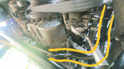
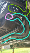
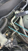
. See below on how the cooler loop should sit:
20250225-132401.jpg

With this in place, come around to the nearside of the engine bay and look forward:
20250217-201233.jpg
This is where you may notice there is no way to route the cooler return loop hoses - it seems that the E46 has no structural support brace like we zedders do, so they get it easy here. So what I have done is cut away a small piece of the support brace (which I marked in white paint), and you may well wince at it but this is the price of a factory fit! I don't believe it compromises the structural integrity of the brace since this piece doesn't mount anywhere so I'm comfortable with this. If you do this though, be careful when cutting out as it is near lots of lovely coolant pipes and air filter boots - I managed fine with an angle grinder with a cut-off disc and finished up with a narrow-head belt sander, and finally a dab of black Hammerite paint to thwart any future rusting. If you don't want to do this, then that is fair enough, but I can't comment further on where you could place your cooler return lines; please consult others who have completed the conversion differently to get a better idea.

Onwards!

With this piece cut out, there is now space to connect the steering rack line to the lower cooler return loop end. You'll want to connect this first as you won't have access to connect it if the upper line from the cooler loop is in the way. So, the photos get a little tricky to see as I took them when I had the air filter housing in place, but starting at the steering rack, follow the yellow line up (this denotes the line to follow into the next two photos) behind and then above the power steering pump, bringing it forward to the cut-out of the support brace. (note the white marker I have put in the right-most photo showing where this used to be).
20250226-101440.jpg 20250225-132058.jpg 20250225-132242.jpg
I have taken the photos with the upper reservoir line going to the cooler (highlighted in red), so visibility isn't the best but the yellow line goes between the support brace cut-out and the coolant expansion tank - same for the red hose. It has to bend down slightly to the level of the cooler return loop but this shouldn't affect operation as this is the low pressure side of the system. Ideally you'd cut out the lower part of the support brace, but any lower than this and you're cutting into the mounting face for the bolts which connect the brace to the chassis rails - so this slight bend will have to do! It's worth it at this point to cover the cut-out with some rubber trim if you have some, or wrap the pipe in some tough material to protect from abrasion. Then it should just push-fit onto the cooler return loop using the connector already present on the line. Now we have the steering rack connected to the cooler, onto the reservoir line to the cooler.

Referencing photos 1 & 2 from the above cooler to rack section, now follow the red lines denoting the cooler line to reservoir. Since you already fitted the fluid reservoir, you will see the smaller of the two pipes at the bottom of the reservoir and this is meant to connect to the cooler return loop via the hose which hopefully you'll have picked up in the parts list to begin with. Now, you may have luck with the hose being just pliable enough to make up the distance between the reservoir and the upper cooler return loop connection - assuming you have also mounted your cooler return loop in this same position.

If you do, it's a simple push-fit onto the cooler return as in the photo below, just like you do with the lower cooler loop fitting for the line which comes from the rack. You'll see on your cooler loop that there is a lip for each hose push-fit connector to get past. This is what creates the seal, so make sure you push the connector on as much as you can. At this point, to support the cooler loop when you push the connector on - because, remember that the loop is loose on this end) you can reach through the kidney grille you removed earlier to push the loop from that side, allowing enough pressure to get the connector on properly.
20250225-130741.jpg

If however your hose isn't quite long enough (don't worry, it's how you use it that counts), like mine wasn't - I couldn't comfortably bend the hose enough to make up the distance - then you can do what I did which is cut the pipe into two pieces and join them via a piece of mild steel tubing (which you can see in the photo below highlighted in red and is the same material as the cooler return loop) which I believe is 12.4mm outer diameter. This works with the hose which is 12.4 inner diameter roughly.
20250225-132401.jpg
The two hose pieces are pushed onto the connecting mild steel pipe and then clamped down in three places to ensure no leaks arise. Since this is only the low pressure side of the system, the third hose clamp might be overkill but I prefer to go overboard than have to deal with a PS fluid clean up! Talking about hose clamps, make sure you put one on the connection between the hose and fluid reservoir.

So with the reservoir now connected on the return side, it's time for the final connection which is just the reservoir feed hose which goes to the power steering pump. Now I haven't taken a photo of this unfortunately, but with the air filter housing removed, you should be able to get an idea from the below photos following the green lines.
20250217-201229v2.jpg 20250225-131934v2.jpg 20250225-132058v2.jpg

This hose is larger and it fits of the corresponding larger connection on the underside of the reservoir. Fit it, then route the hose down and around/behind the alternator where you can bring it to the back of the power steering pump and slide it on. Like the with the other reservoir hose, secure the hose to both the reservoir and the pump using hose clamps (these will need to be bigger to accommodate the larger diameter hose).

That should now be all of your connections made (remember to reconnect your tie rod assemblies!) and the system is ready to be filled with fluid properly - follow this guide for that process: https://tinyurl.com/ytf4yh8s. Then take your new belt and fit it onto the driven pulley assembly, by rotating the tensioner pulley you used at the start of this conversion, and looping the drive belt in the correct manner. There is information on how to do this in one of the first mentioned thread posts by other members, so take a look there for how to route the belt.

Once that is done, you'll need to bleed the system and refill the power steering fluid as necessary - again, the above linked guide will tell you how to do this. There are forum posts I believe on the correct power steering fluid to use and I chose this from Halfords: https://tinyurl.com/5r5kj87c. There are specifications for what fluid to use, but I trust this meets those standards and will work just fine.

Now, while the hydraulic system is all there and ready to operate (if you were to start your car now, you'd hear the extra effort the engine has to put in to accommodate for power drain when turning the wheel left and right), you still have the matter of the EPS motor on the upper steering column assembly. Now, I have yet to do this part, but there are again plenty of forum posts about this. I may well be putting a question or two out there to you guys that have! ;).

From my understanding, you have a few options:

A) Leave the EPS motor in its place and remove the fuse associated with this system. This will deactivate electronic power assisted steering, but will cause the fault lamp to illuminate on your dashboard, becoming an MOT failure in the UK if you don't sort it out - I know people put black tape or whatever over the light. But there is then the matter that your steering column is still coupled in some manner to the EPS motor, which without power, the friction of which is something you are now going to have to overcome.
B) Drop the steering column, remove the EPS motor/ecu entirely and either get the black tape out for that pesky fault light or get it properly coded out (I've heard Zed Coding in Birmingham will provide this service). The potential issue here to some - myself included - is that without the EPS ecu, you'll lose the sport button mode if you have it, meaning no exhaust valve actuation and no throttle response adjustment via the button.
C) Do the same as above, removing the EPS motor but leaving the ecu in place, removing both the issues of frictional drag on the steering column from leaving the motor in place, and avoiding any fault lights from appearing, as well as keeping the functionality of the sport button. This is my understanding at least, so it might not be entirely accurate but I believe others will correct me on this (@enuff_zed I'm looking at you ;))

And that's all chaps, hope this helps! It was meant to be a short write-up but somehow this has taken me a good 6 hours to compile, so hopefully it's of some use to someone haha. I'm sure at this point there's going to be some mistakes in how I've written up the order/photos of the process, so feel free to ask for clarification!
 

Attachments

  • 20250226-101440.jpg
    20250226-101440.jpg
    11.3 KB · Views: 3
  • 20250225-132058.jpg
    20250225-132058.jpg
    8.9 KB · Views: 3
  • 20250217-201229v2.jpg
    20250217-201229v2.jpg
    10.8 KB · Views: 3
  • 20250225-131934v2.jpg
    20250225-131934v2.jpg
    12.5 KB · Views: 3
  • 20250225-202855.jpg
    20250225-202855.jpg
    8.8 KB · Views: 3
  • 20250225-132836.jpg
    20250225-132836.jpg
    10.6 KB · Views: 3
Wow, that thread has taken you a long time to write up. Well done! I also struggled back in 2016 to get the hydraulic fluid cooler to fit. You said you got a kit. Where did you manage to get one? Thanks again for the write-up
 
Excellent write up, well done!
Regarding the EPS motor, I cannot claim to be an expert in exactly this aspect of it having never done a hydraulic conversion.
However, to address your options using my 'incomplete' experience:

A) Whilst a worm drive can turn a cog, the other way round doesn't work very easily, so yes you will suffer a lot of resistance. The fault light will be an MOT issue as you say. So this is not a viable alternative IMO.
B) Not sure what exhaust valve actuation you mean? Not something fitted to the E85/6 AFAIK? But yes the sport facility passes through the EPS ECU, so you would lose that. You also need to look carefully at the Traction Control/Stability aspects. One of the inputs to this is the Steering Angle Sensor, sent via the Canbus to the EPS ECU. Without the EPS ECU where else does the SAS report to? I'm not sure this is a 'safe' solution. It may even put on the Traction Control light?
C) This would work, but I'm not sure exactly how the ECU and motor connect. You may up introducing more problems if the ECU cannot see the motor. Also, you would need to find a way to support the ECU.

I do have a 'D' suggestion................
Remove the motor and cut off the drive shaft that engages with the column, then bolt the castrated motor back on.
Everything remains as it was. The system functions in exactly the same way, only now it spins the EPS motor to no effect as it is not engaged with the column. Apart from that mechanical connection, everything else works in exactly the same way.

There is one drawback however:
What happens if/when the EPS ECU fails?
ECU Testing could repair it, but they set it up on a test rig before and after the repair. So sending them a standalone ECU, or a castrated motor assembly will not work and I suspect they would simply return it.
I think if that were me I would go with my option 'D' and source a good secondhand motor, castrate that and fit it.
 
raymond.harper said:
Wow, that thread has taken you a long time to write up. Well done! I also struggled back in 2016 to get the hydraulic fluid cooler to fit. You said you got a kit. Where did you manage to get one? Thanks again for the write-up

Yeah that cooler loop was a pain haha!

And it was a second-hand kit provided by a member on the facebook group. He might be on here, FB name is Scooby (he's done a great S54 swap into his E86) he'd done the hydraulic conversion already on his car but ended up selling it as a full kit when putting the S54 in, as that came with the factory Z4M steering set up. So I promptly drove a few hours north to fetch it.
 
enuff_zed said:
Excellent write up, well done!
Regarding the EPS motor, I cannot claim to be an expert in exactly this aspect of it having never done a hydraulic conversion.
However, to address your options using my 'incomplete' experience:

A) Whilst a worm drive can turn a cog, the other way round doesn't work very easily, so yes you will suffer a lot of resistance. The fault light will be an MOT issue as you say. So this is not a viable alternative IMO.
B) Not sure what exhaust valve actuation you mean? Not something fitted to the E85/6 AFAIK? But yes the sport facility passes through the EPS ECU, so you would lose that. You also need to look carefully at the Traction Control/Stability aspects. One of the inputs to this is the Steering Angle Sensor, sent via the Canbus to the EPS ECU. Without the EPS ECU where else does the SAS report to? I'm not sure this is a 'safe' solution. It may even put on the Traction Control light?
C) This would work, but I'm not sure exactly how the ECU and motor connect. You may up introducing more problems if the ECU cannot see the motor. Also, you would need to find a way to support the ECU.

I do have a 'D' suggestion................
Remove the motor and cut off the drive shaft that engages with the column, then bolt the castrated motor back on.
Everything remains as it was. The system functions in exactly the same way, only now it spins the EPS motor to no effect as it is not engaged with the column. Apart from that mechanical connection, everything else works in exactly the same way.

There is one drawback however:
What happens if/when the EPS ECU fails?
ECU Testing could repair it, but they set it up on a test rig before and after the repair. So sending them a standalone ECU, or a castrated motor assembly will not work and I suspect they would simply return it.
I think if that were me I would go with my option 'D' and source a good secondhand motor, castrate that and fit it.

Not to put any pressure on you of course haha; sorry! But you offer some good insights there so I don't believe it was misplaced lol

Yeah, option A is a no.

Option B you mention about the steering angle sensor, that's an interesting thing I hadn't considered. I know the steering angle sensor is a separate unit to the EPS motor in terms of its actual location, so I assumed it would have its own paths back to the main ECUs (I don't pretend to know anything about comms systems in cars so bear with here) but it makes sense that the EPS ECU is responsible for it now you mention it. The exhaust valve I was referring to is just a butterfly valve within the exhaust I believe which, with Sport button activated, will open up to allow more noise from the exhaust - it makes a marked difference for sure.
What I'm curious about is, having tested the car for a short time with the EPS fuse pulled out, deactivating that system, I wonder if that turns the EPS ecu off? Traction control (the one linked with the triangle warning on the dash which flashes when you lose grip I think it is) seemed normally operative in the time I drove without the EPS fuse in, so if the EPS ECU does get switched off in doing this, I'm lead to thinking the Traction Control works fine - can't comment on Stability control as yet but I would imagine it follows suit. So I will continue to investigate option B here.

Option C I will also look further into if option B doesn't work. Keeping the ECU but not having it be able to 'read' the motor may introduce problems as you say. Perhaps it just needs a power signal to run through the motor to assume nothing is amiss - again, I don't know any of this without looking so this is all assumptions for now.

I understand option D is quite common and seems to work most simply with as little faffery as possible, but I don't like the idea of hacking the motor up haha. And yeah like you say, getting a second-hand motor can't be too difficult, what with all those of us switching to hydraulic they're likely to be easy enough to source.

If cutting the motor shaft has to be done then it will be, but I would kick myself if I didn't at least explore the other less intrusive options first.
 
[ref]PhilMGCollins[/ref], seems you have a good plan and the time to explore all the options.
Be interesting to hear your findings around Option B.
However, I am still pretty much convinced the exhaust valve only came in with the E89?
 
Yeah, have had the Z4 off the road for the past month doing the hydraulic conversion along with some other preventative maintenance bits - water pump, thermostat, engine & transmission mounts, front main seal. Yet to do it but I need to drop the subframe to do the sump pan gasket as it's leaking horrendously!

I haven't looked up info on the exhaust valve, but it was something on my brother's old E46 330ci - so same engine and exhaust as far as I know, he locked the valve to be open at all times. I do have a stainless catback exhaust so perhaps it enhances the otherwise potentially subtle noise difference when Sport mode is activated, but it definitely changes the note. I can't imagine the factory Sport button working in conjunction with a non-standard exhaust system to open a valve like that
 
enuff_zed said:
C) This would work, but I'm not sure exactly how the ECU and motor connect. You may up introducing more problems if the ECU cannot see the motor. Also, you would need to find a way to support the ECU.

Got the column off today to get a good look at the motor/ECU and minus the four bolts holding the ECU to the motor casing, I'm a bit lost as to how they then remain connected. Firstly tried gently prying up the ECU but it gets maybe 10mm apart from the motor casing and doesn't seem to want to go further - without breaking it feels like.

Have I got it right that you've had the motor/ECU separated? I think I read that from a past thread. You say here you're not sure how they connect and I've taken that to mean how they communicate but maybe I've misinterpreted lol
 
Roger, my mistake!

I've found another forum thread which demonstrates how to separate the motor & ECU so will be giving that a go tonight. Will plug the ECU in without the motor and see what happens - initial hypothesis is the ECU only sends power and doesn't receive any signals back directly from the motor (again, that's based on nothing but wishes haha)
 
You can separate the black box from the motor as that's what I had done to mine. You need to remove the black putty over the wiring terminals to disconnect them but it works fine. You need to remove the LED from the dash cluster which is a 60 second job but the sport button still works etc.
 
Ahh so it can be done! So you've just got the EPS module mounted back up in the car, without the motor?

When you say to remove the black putty, is that on the three brass-plated screw terminals going from the EPS module to the motor? I'm looking at this for reference: Post by Rhamberg, photo 3 - https://z4-forum.com/forum/viewtopic.php?t=103782#top

Ideally I'd not be wanting to remove the lights and instead have them coded out if possible. So it still throws up a fault light despite the EPS module being reinstalled?
 
Yup back in without the motor.
The black putty is over the connections in his photo number 8.
file.jpg

It does show an error on the dash without the motor, however the benefit to keeping the ecu attached means you still get the sport button working. I didn't investigate coding it out, the bulb was so easy to remove.
 
Perfect! Haven't got to that bit yet but that seems easy enough. I spent most of last night trying to pull the module off by force - only after I found Rhamberg's thread did I see that those terminals are bolted down haha

That's the main thing for me; keeping Sport mode working. Have you experienced any niggles with things like traction/stability control since you did this?
 
That's what we want to hear, thanks for the reassurance!

Initial impressions of the hydraulic steering while the motor was still installed (deactivated by pulling fuse) were a bit underwhelming, so fingers crossed this does the trick
 
thecremeegg said:
Yup back in without the motor.
The black putty is over the connections in his photo number 8.
file.jpg

It does show an error on the dash without the motor, however the benefit to keeping the ecu attached means you still get the sport button working. I didn't investigate coding it out, the bulb was so easy to remove.

Got the motor and module separated now, thanks. What did you do to secure the little ribbon cable sensor? Seems quite fragile minus the cylindrical housing, so I'm thinking to just tape it tight against the module housing.
 
Back
Top Bottom