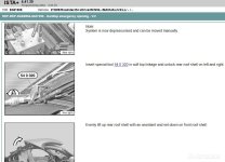
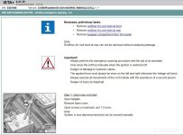
A68C, roof is closed and latched, and will not budge with either button - just get the blinking red light. I'm confident I can repair the wiring, but I can't get the roof open. ISTA says that it is necessary to damage the interior of the rear shell to open it now. Does anybody have a better idea? TIA!
You are using an out of date browser. It may not display this or other websites correctly.
You should upgrade or use an alternative browser.
You should upgrade or use an alternative browser.
Is this the only way to open the roof now?
- Thread starter r0x
- Start date
OK. My trunk and windows actually work fine. But in the video, he opens the rear shell by jumping the signal wires for the two microswitches, essentially fooling the CTM into thinking they're both OK. My problem however is the rear shell Hall sensor. Could I perform the same trick by jumping the rear shell Hall sensor signal wire to one of the other Hall sensor signal wires? It seems logical but I don't know if I'm going to fry something.
If it won't open it's possibly seeing an open circuit broken wire to the sensor.
If you had another sensor perhaps it could be wired or plugged into module in the boot to bypass the sensor, but bring back the continuity.
Not a simple matter of just bridging any wires on hall sensor.
Look for this in US.
https://www.lllparts.co.uk/product/bmw-54347190735-hall-sensor/mpn/54347190735

Another idea jump wires from hall sensor all the way back to control module to bypass any broken wires.
I know i had broken wire on the hall sensor "roof panel 2 packed".
I threaded in new wires to bypass the old wire, i had no idea where it broke, too hard to remove wires, so paralleled new wires and soldered to hall sensor.
If you had another sensor perhaps it could be wired or plugged into module in the boot to bypass the sensor, but bring back the continuity.
Not a simple matter of just bridging any wires on hall sensor.
Look for this in US.
https://www.lllparts.co.uk/product/bmw-54347190735-hall-sensor/mpn/54347190735
Another idea jump wires from hall sensor all the way back to control module to bypass any broken wires.
I know i had broken wire on the hall sensor "roof panel 2 packed".
I threaded in new wires to bypass the old wire, i had no idea where it broke, too hard to remove wires, so paralleled new wires and soldered to hall sensor.
The top hall sensor (HS) can't be bridged to any other signal! It detects the arrival of the rear roof shell on the front.
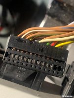
But putting an external HS onto the correct wires directly on the 26pole plug at the CTM might do the trick. The sensor wires on the plug are organized in parallel: 3-16, 4-17, 5-18 ,...
For hall sensors you have to care about the pin orientation as well: colour is power supply, brown is the signal itself.
Sensors can be simulated as well with resistors: 570 ohms or 2.770 ohms.
But that's not a simple playground!
This week I've tested bridging a microswitch coupling lock from the left to support a defective one on the right. It didn't work!
The CTM always checks the current(!) on each sensor line. If you connect one CTM sensor port to another by a bridge, the sensor current deviates too much and the CTM will block any operation.
The CTM always checks the current(!) on each sensor line. If you connect one CTM sensor port to another by a bridge, the sensor current deviates too much and the CTM will block any operation.
 Scottish Borders
RobbiZ4 said:This week I've tested bridging a microswitch coupling lock from the left to support a defective one on the right. It didn't work!
The CTM always checks the current(!) on each sensor line. If you connect one CTM sensor port to another by a bridge, the sensor current deviates to much and the CTM will block any operation.
Disappointing that our token rocket scientist was defeated by the CTM…


Please keep trying for all of us pls..

Well, this was to demonstrate some guys, that the DiagnoseDan solution in his famous E89 video doesn't work as a general option.B21 said:Disappointing that our token rocket scientist was defeated by the CTM…
My Y3 diagostic tool instead is able to suggest the correct signals to the CTM in every case.
https://z4-forum.com/forum/viewtopic.php?p=1912298#p1912298
RobbiZ4 said:Well, this was to demonstrate some guys, that the DiagnoseDan solution in his famous E89 video doesn't work as a general option.B21 said:Disappointing that our token rocket scientist was defeated by the CTM…
My Y3 diagostic tool instead is able to suggest the correct signals to the CTM in every case.
https://z4-forum.com/forum/viewtopic.php?p=1912298#p1912298
My faith has been restored
flybobbie said:If you had another sensor perhaps it could be wired or plugged into module in the boot to bypass the sensor, but bring back the continuity.
You know, I *do* have a few Hall sensors here in the garage!
RobbiZ4 said:But that's not a simple playground!
Hold my beer Ima try somethin'.
Will do.r0x said:Hold my beer Ima try somethin'.
 :icb:
:icb:I think it would be advisable to have a spare micro switch and hall sensor which can be temporarily wired into the CTM to both troubleshoot and operate the top into a serviceable position. I'm currently putting together such a kit, along with some spare wire, to keep ready for eventual convertible top failure events. Basically I don't ever want to screw around with releasing hydraulic pressure and manually lifting roof sections.
javis20 said:I think it would be advisable to have a spare micro switch and hall sensor which can be temporarily wired into the CTM to both troubleshoot and operate the top into a serviceable position. I'm currently putting together such a kit, along with some spare wire, to keep ready for eventual convertible top failure events. Basically I don't ever want to screw around with releasing hydraulic pressure and manually lifting roof sections.
Look forward to the design

flybobbie said:Something i not noticed on my Foxwell reader if i can obd wise operate a switch or sensor in real time to fool the system, bypass the continuity check..
If roof in boot when fails, all a bit tricky.
That's a good question. I'm wondering the same with BimmerGeeks ProTool. I'm going to contact them to get an answer.
Which connectors exactly?r0x said:Did you know there are different size pins for these electrical connectors?
Are hallsensors and microswitches use male MQS pins in their connector housings.
RobbiZ4 said:Which connectors exactly?
Are hallsensors and microswitches use male MQS pins in their connector housings.
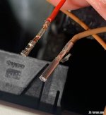
I mean the metal pins that pull out of the black plastic connector that goes into the CTM from the roof. In the close-up, the brown wire is the factory pin that I pulled out of the black connector, while the red one (obviously much smaller) is the one I crimped onto my spare Hall sensor.
This is where I got the "small" connector from: https://a.co/d/iB1VLPt
... and this is what I bought as a replacement: https://a.co/d/eYzhsU4
I never heard of MQS before. Do you think the 3.5mm pins in the second link above will work? Or should I buy something else?
I should add the size difference is enough that the small pins don't stay in the black plastic connector - they just slide out. So they won't work.
Attachments
Similar threads
- Replies
- 16
- Views
- 1K
- Replies
- 2
- Views
- 237