Bunnyboileravoider
Member
Ladies & Gents,
I'm stuck, and would really appreciate help in identifying what I'm doing wrong. Hopefully this offers enough context.
Vehicle: 2006 2.0i facelift E85 (absolute entry level vehicle i.e. cloth seats, no extras, not even interior footwell lights (let alone USB ports)
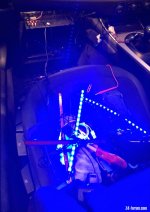
Objective: 2 x independent USB ports, active only when ignition is on, but permanently fixed (for interior LED footwell lights)
Intention: tap inline using 3A fuse into one of the spares, or piggy back fuse with one of the existing 'ignition on' 5A fuses, connect that to voltage reducer with 2 x USB ports
Equipment:
- piggy back connector (https://www.halfords.com/tools/fuse...p_IO1LaPfoh3tQzAcqSqwy_yFakihc2UaArcrEALw_wcB),
- 12V to 5V/3A connector (https://www.amazon.co.uk/gp/product/B06XSCCLCD/ref=ppx_yo_dt_b_asin_title_o00_s01?ie=UTF8&psc=1)
- multiple fuses
- multimeter
Ideas already tried & discarded:
- use cigarette lighter socket? Always on, looks ghastly, ashtray cover always open etc. etc. Even if I hid it under the trim, it's still 'always on'.
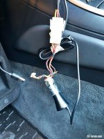
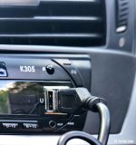
- use USB port on stereo? Despite stereo being 'ignition only', it retains some power for clock etc. and testing revealed the USBs are always live. Even if they weren't, it would require rerouting cable through fascia, all holes I'd rather not create.
Story so far...
As these pictures show, I've opened it all up (thanks to the absolute HEROS in this forum who've been there and got the t-shirt many years ago and since)
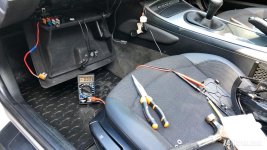
identified the screw recommended by predecessors as a perfect chasis point,
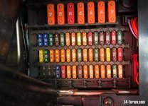
changed that screw for a stainless steel one and added a washer for good measure, bared the black wire for Earth and screwed it in tight. I've crimped the red Live ends together tightly (it's not going anywhere), and felt very pleased with myself...
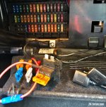
...except that it still doesn't work, neither with the ignition off, nor on. I've tried various 5A fuses (believe it or not there are fuses in the ports where I don't have those accessories, such as heated seats, parking sensors etc., so that really didn't help either). I've referred to the ste-by-step guide in this thread (https://z4-forum.com/forum/viewtopic.php?f=2&t=104224&hilit=iphone&start=15), and about 3 others (the fuse diagrams showing 'always on' and 'ignition only' were brilliant in theory, by the way, so thank you).
I'm just not sure what the hell else to try :headbang: :headbang: :headbang:
Thanks in advance for any help
I'm stuck, and would really appreciate help in identifying what I'm doing wrong. Hopefully this offers enough context.
Vehicle: 2006 2.0i facelift E85 (absolute entry level vehicle i.e. cloth seats, no extras, not even interior footwell lights (let alone USB ports)
Objective: 2 x independent USB ports, active only when ignition is on, but permanently fixed (for interior LED footwell lights)
Intention: tap inline using 3A fuse into one of the spares, or piggy back fuse with one of the existing 'ignition on' 5A fuses, connect that to voltage reducer with 2 x USB ports
Equipment:
- piggy back connector (https://www.halfords.com/tools/fuse...p_IO1LaPfoh3tQzAcqSqwy_yFakihc2UaArcrEALw_wcB),
- 12V to 5V/3A connector (https://www.amazon.co.uk/gp/product/B06XSCCLCD/ref=ppx_yo_dt_b_asin_title_o00_s01?ie=UTF8&psc=1)
- multiple fuses
- multimeter
Ideas already tried & discarded:
- use cigarette lighter socket? Always on, looks ghastly, ashtray cover always open etc. etc. Even if I hid it under the trim, it's still 'always on'.

- use USB port on stereo? Despite stereo being 'ignition only', it retains some power for clock etc. and testing revealed the USBs are always live. Even if they weren't, it would require rerouting cable through fascia, all holes I'd rather not create.

Story so far...
As these pictures show, I've opened it all up (thanks to the absolute HEROS in this forum who've been there and got the t-shirt many years ago and since)

identified the screw recommended by predecessors as a perfect chasis point,

changed that screw for a stainless steel one and added a washer for good measure, bared the black wire for Earth and screwed it in tight. I've crimped the red Live ends together tightly (it's not going anywhere), and felt very pleased with myself...

...except that it still doesn't work, neither with the ignition off, nor on. I've tried various 5A fuses (believe it or not there are fuses in the ports where I don't have those accessories, such as heated seats, parking sensors etc., so that really didn't help either). I've referred to the ste-by-step guide in this thread (https://z4-forum.com/forum/viewtopic.php?f=2&t=104224&hilit=iphone&start=15), and about 3 others (the fuse diagrams showing 'always on' and 'ignition only' were brilliant in theory, by the way, so thank you).
I'm just not sure what the hell else to try :headbang: :headbang: :headbang:
Thanks in advance for any help
