
There will continue to be some confusion about installing Aux In, Nav, and Bluetooth without conflict. They share the same head unit connector, but each has their own set of pins. Mau has shared a great diagram in German, but it's a little hard to read. The WDS has the information, but using the WDS is confusing. I've compiled this information here so that it is all available in one place. I'm sure it will be found useful. Applies to all E85 and E86 audio systems, all levels, basic, Hi-Fi, Carver. Includes wire size, colour, max. current info.
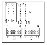
If the code above box has annoying line breaks, try making your browser window wider.
Search terms: business radio pin outs out pinouts pinout assignment navigation auxiliary input wiring color area output signal CD changer compact disc plug front rear speaker amp amplifier phone telephone
Code:
BMW E85/E86 Business Radio Pin Outs

Pin assignments at black plug connector X18805 pins 1-8 (A)
Pin assignments at black plug connector X18126 pins 9-16 (A)
Pin Type Description / Signal type / Connection / Area mm^2 / Colour/Tracer-Option Level
1	A	Signal, AF radio, rear right +	Amplifier or Speaker	0.75 Blu/Viol Basic (Blu/Blk Hi-Fi)[not used Carver]
2	A	Signal, AF radio, front right +	Amplifier or Speaker	0.75 Blu/Red
3	A	Signal, terminal 50 via vehicle immoblizer	Amplifier or Speaker	0.75 Yell/Red
4	A	Signal, AF radio, rear left +	Amplifier or Speaker	0.75 Yell/Viol Basic (Yell/Blk Hi-Fi)[not used Carver]
5	A	Signal, AF radio, rear right -	Amplifier or Speaker	0.75 Blu/Grn Basic (Brn/Org Hi-Fi)[not used Carver]
6	A	Signal, AF radio, front right -	Amplifier or Speaker	0.75 Blu/Brn Basic (Brn/Org Hi-Fi Carver)
7	A	Signal, AF radio, front left -	Amplifier or Speaker	0.75 Yell/Brn Basic (Brn/Org Hi-Fi Carver)
8	A	Signal, AF radio, rear left -	Amplifier or Speaker	0.75 Yell/Grn Basic (Brn/Org Hi-Fi)[not used Carver]
9	E/A	K-bus signal	K-bus connector	0.5 Wht/Red/Yell
10	E	Telephone mute circuit	Cellular telephone	0.35 Wht/Brn
11	E	Signal Telephone on	Cellular telephone	0.35 Wht/Grn
12	M	Ground	Ground point	2.5 Brn
13	E	Aerial switching signal	Aerial amplifier or aerial diversity	0.5 Wht
14	E	Activation, left bi-xenon headlight	Light switch cluster	0.5 Grn/Red
15	E	Terminal 30	Fuse F50 Unsitched power	2.5 Red/Yell
16	E	Terminal R	Fuse F47 Switched power	0.75 Viol/Wht

Pin assignments at beige plug connector X13321 (B)
Pin Type Description / Signal type / Connection / Area mm^2 / Colour/Tracer
1	 	Not used {headphones left}
2	E	Signal, CD changer AF -, common	CD changer	0.5 Wht/Brn
3	 	Not used {headphones Common}
4	 	Not used {VCR right}
5	 	Not used {VCR left}
6	 	Not used {VCR common}
7	 	Not used {headphones right}
8	E	Signal, CD changer AF +, left	CD changer	0.5 Wht/Red
9	E	Signal, CD changer AF +, right	CD changer	0.5 Wht/Blu
10	 	Not used {TV right}
11	 	Not used {TV left}
12	 	Not used {TV common}

Pin assignments at grey plug connector X13598 (C)
Pin Type Description / Signal type / Connection / Area mm^2 / Colour/Tracer
1	 	Not used {tape left+}
2	 	Not used {tape left-}
3	E	AF signal, left	AV socket	0.35 Blk
4	E	AF signal, right	AV socket	0.35 Yell
5	A	Navigation signal Positive activation	Navigation system or Video module	0.5 Blu/Red
6	E	Signal, telephone AF +	Cellular telephone	0.75 Blk/Wht
7	 	Not used {tape right+}
8	 	Not used {tape right-}
9	 	Not used (Radio Nav Only 0.5 Wht/Grn)
10	M	Shield	AV socket
11	A	Navigation signal Negative activation	Navigation system or Video module	 0.5 Yell/Brn
12	E	Signal, terminal 50 via vehicle immoblizer	Cellular telephone	0.75 Blk/Brn

Assignments at cable shoe X13342 (Not shown in diagram)
Pin Type Description / Signal type	Connection
1	A	Signal, aerial reception	Aerial amplifier or aerial diversity

{Curly braces = Obsolete, for info only}

				Max
mm^2 	AWG Amps
0.35 	22 	3
0.5 	20 	5
0.75 	18 	7.5
1.0 	17 	10
2.5 	13 	15
4.0 11 20Search terms: business radio pin outs out pinouts pinout assignment navigation auxiliary input wiring color area output signal CD changer compact disc plug front rear speaker amp amplifier phone telephone
