Not joined yet? Register for free and enjoy features such as alerts, private messaging and viewing latest posts and topics.

E85 / E86 BMW Z4 – Android tablet integration

Post Reply
danergo
Newbie
Newbie
Posts: 4
Joined: Wed Apr 06, 2016 12:06 pm

E85 / E86 BMW Z4 – Android tablet integration

Post by danergo » Mon Oct 22, 2018 10:08 pm

Hello, js_online,

I followed your tutorial to build a similar system as yours. I'm stuck with the motor board actually.

I did not want to remove the original connector from the L9935 board's wire, because all the necessary signals (for SPI) are presented on the connector (except /EN pin on the L9935 - /EN is pulled low automatically as the board receives +5V power supply).
(They all have a small resistor and a filtering capacitor, but anyway the pins on the connector are going to the L9935 itself.)

However I can't succeed with Arduino. (I'm using Mega2560, because I don't have any UNOs here).
Of course, on the Mega, the SPI pins are located differently, that's not an issue.
The very first SPI message arrives to the L9935 and it executes it, but all the following SPI commands are skipped.

But if I restart the arduino, the first SPI message arrives again to L9935 and it executes it.
(Technically: I don't need to 'reset' the motor board to receive an SPI command and execute it. Somewhy arduino seems to stuck in some SPI magic)

Could you help me in this manner?

Thanks very much!
js_online wrote: Tue May 19, 2015 12:54 am I'd like to share details of setup using Arduino R3 UNO and native L9935 stepper motor driver using Serial Peripheral Interface (SPI) (without using Arduino Motor Shield).

User avatar
McKoval
Member
Member
Posts: 479
Joined: Thu Mar 31, 2011 10:58 am
Location: Krakow

E85 / E86 BMW Z4 – Android tablet integration

Post by McKoval » Tue Oct 23, 2018 11:15 am

danergo wrote: Mon Oct 22, 2018 10:08 pm I did not want to remove the original connector from the L9935 board's wire, because all the necessary signals (for SPI) are presented on the connector (except /EN pin on the L9935 - /EN is pulled low automatically as the board receives +5V power supply).
(They all have a small resistor and a filtering capacitor, but anyway the pins on the connector are going to the L9935 itself.)
Hi,
could you please share photos (and schemes if its possiblle), how did you connect wires to the connector?

I'm stuck at the stage of soldering into the board, and as I don't have time to search for help, the project got stalled almost a year ago..
Image

js_online
Newbie
Newbie
Posts: 25
Joined: Mon May 18, 2015 11:49 pm

E85 / E86 BMW Z4 – Android tablet integration

Post by js_online » Fri Dec 07, 2018 1:45 am

danergo wrote: Mon Oct 22, 2018 10:08 pm The very first SPI message arrives to the L9935 and it executes it, but all the following SPI commands are skipped.
As I see from the code activateL9935EN() function re-activates device before each set of commands. You can check L9935 datasheet for details, but this is done for the purpose. The main thing is achieve at least one move of motor, this will indicate that you L9935 board is wired properly and SPI interterface is initialized properly too. Write simple code and make it work.
Simple pseudo-code of what I mean is below:

Code: Select all

#include <SPI.h>
#include <EEPROM.h>
...
//Setup Wiring
//ICSP Pins for Arduino Nano
//1 - MISO  - Arduino Uno Pin 12
//2 - VCC+  - eq used
//3 - SCK   - eq Arduino Uno Pin 13
//4 - MOSI  - eq Arduino Uno Pin 11
//5 - Reset - Not used
//6 - GND   - common ground, can be used as second ground as Arduino Uno had 2 GNDs nearby VCC pin, but only one is present for Arduino Nano 
int EN=9;        //Enable L9935 (Low Active)
...
//setup section
//Setup SPI
  SPI.begin();                           //wake up the SPI bus.
  SPI.setBitOrder(MSBFIRST);             //data to be sent MSB (most significant byte) first
  SPI.setClockDivider(SPI_CLOCK_DIV16);  //1Mhz SPI clock 16/16
  SPI.setDataMode(SPI_MODE3);  
...
//Loop section
//Code 
  //Activating L9935
  digitalWrite(EN, HIGH);     //disable L9935 
  delay(1);
  digitalWrite(EN, LOW);      //enable L9935. Falling slope of EN activates the device. After ten.sck the device is ready to work.
  delay(1);

//One Move to open screen
  setSPIValue(15);    //00001111 CH A enabled, polarity=HIGH (Current=900mA). CH B disabled.
  setSPIValue(56);    //00111000 CH A disabled. CH B enabled, polarity=LOW (Current=900mA).
  setSPIValue(6);     //00000110 CH A enabled, polarity=LOW (Current=900mA). CH B disabled. 
  setSPIValue(57);    //00111001 CH A disabled. CH B enabled, polarity=HIGH (Current=900mA). 

//End Loop section
...
//function 
void setSPIValue(int SPI_COMMAND)
{
  digitalWrite(SLAVESEL, LOW);        //Start of frame. Falling slope of CSN indicates start of frame. //Arduino Nano used for LL9935 only
  SPI.transfer(SPI_COMMAND);          //Send value (0~255) in decimal format. Data transfer (reading SDI into the register) takes place at the rising slopes of SCK.
  //ERR_CODE = digitalRead(DATAIN);   //Read error code
  digitalWrite(SLAVESEL, HIGH);       //End of frame. //Arduino Nano used for LL9935 only
  delay(1);
}


If you are not comfortable with coding I recommend you to achieve working solution with the same setup first and only after it works you can start migrating step by step to different board. You can buy Arduino UNO for 2.5$ on AliExpress, find somewhere similar motor or buy second used screen as I did to play with and pack original screen for "better times".


Actually long time ago I modified code for Arduino Nano. Board takes less space with the same functionality.
You can buy Nano board on AliExpress for 2$.
I am sharing code here.
ICSP Pins on the side are used for SPI interface on Nano board (google pinout of ICSP to do wiring correctly, these are 6 pins at the mid end of the board). Use exactly the same pins!!!
See comments in code for more details.

Code: Select all

/*==========================================================================================================================
Created by JS online, [email protected]
Last update 04-Jan-2016  v.1.1

Arduino Nano code to operate L9935 stepper motor driver.
Main functionality:
1. Opening screen fully - after ignition is turned on or by open button
2. Closing screen fully - after ignition is turned off or by close button
3. Saving monitor last position to Arduino internal EEPROM memory after ignition is turned off (full step only).
4. Opening by small steps - by step open button
5. Closign by small steps - by step close button (min position is limited to half way - the same as in original behavior)

Enable Serial Monitor Ctrl + Shift + M to see debug messages.
==========================================================================================================================*/
#include <SPI.h>
#include <EEPROM.h>

//L9935 pinning
int SLAVESEL=10; //using digital pin 10 for SPI slave select (used for LL9935 only in NANO version)
//Pins below connected by ICSP 
//int DATAOUT=11;  //using digital pin 11 for MOSI (Master Out Slave In) - master line for sending data to slave
//int DATAIN=12;   //using digital pin 12 for MISO (Master In Slave Out) - the slave sending data to the master
//int SPICLOCK=13; //using digital pin 13 for SCK (Serial Clock) - The clock pulses which synchronize data transmission generated by the master 

//ICSP Pins
//1 - MISO  - Arduino Uno Pin 12
//2 - VCC+  - eq used
//3 - SCK   - eq Arduino Uno Pin 13
//4 - MOSI  - eq Arduino Uno Pin 11
//5 - Reset - Not used
//6 - GND   - common ground, can be used as second ground as Arduino Uno had 2 GNDs nearby VCC pin, but only one is present for Arduino Nano 
int EN=9;        //Enable L9935 (Low Active)

//Board Monitor Buttons
#define OPEN_BUTTON 6       //montior open button full
#define CLOSE_BUTTON 7      //montior close button full
#define STEP_OPEN 4         //montior open button step 
#define STEP_CLOSE 5        //montior close button step

/*Ignition key 12V relay 
R3 UNO, L9935 stepper motor (tablet and other consumers) are powered from +12V ACC (Battery) - X18802 18pin white board monitor socket, Pin 8 = +12V ACC (thru fuse F49), Pin 9 = GND). 
Timer is used for power off delay option. Timer is activated by +12V IGN (Ignition). Power off delay is required to allow close screen after ignition key is turned off and to do not leave 
consumers connected to +12V ACC permanently. Timer logic is the following:
1. after ignition is turned on everything is powered on. Timer Output is operational and connected to +12 ACC: consumers are powered.
2. after ignition is turned off Timer is activated and disconnects +12V Timer Output from +12V Timer Input (ACC) after X seconds (time is adjusted by trimmer and is from 1 sec up to 20 mins). 
After timeout Timer disconnects ACC 12V power, so R3 UNO, L9935 stepper motor and other consumers are also unpowered.*/ 

#define IGN_PWR 8           //igntion 12V power detection. Relay connected to 12V iginition power connects/disconnects GND with IGN_PWR wire.
int ignState = 0;
  
//Delays - miliseconds used for various delays
int DELAY_SS=1;         //very short delay
int DELAY_S=16;         //short delay
int DELAY_N=100;        //standard delay
int DELAY_L=500;        //long delay
int DELAY_LL=2500;        //long delay
int DELAY_INIT=5000;    //delay on ignition

//Monitor positioning: over movement protection and last position. Last saved position works by operating buttons only. Positioning is not tracked if monitor is adjusted manually.
//Last position of monitor is saved after ignition 12v power is turned off. Last position of monitor is restored after ingnition 12v power is tuned on.
float POS_CUR=0;          //monitor current positon full step counter
int POS_CUR_HS=0;         //monitor position half step counter
float POS_STEP_HS=0.25;   //monitor position half step
int POS_STEP_MIN=7;       //limiting min half step position
float POS_MAX=10.7;       //monitor maximum position
int POS_CUR_SAVED=0;      //monitor saved position (full step only)
int POS_CUR_ADDR=0;       //EEPROM address for storing current position (full step only)
int FINE_DOWN=0;          //fine tuning move down flag

//int ERR_CODE;    //read L9935 SPI error code in case if DATAIN pin is connected

// the setup function runs once when you press reset or power the board
void setup() {
  
  //Arduino Nano 
  //SDI, SDO, SCK processed thru ICS
  //pinMode(DATAOUT, OUTPUT);          //SDI
  //pinMode(DATAIN, INPUT);            //SDO not used
  //pinMode(SPICLOCK, OUTPUT);         //SCK
  pinMode(SLAVESEL, OUTPUT);           //CSN
  pinMode(EN, OUTPUT);                 //Enable LL9935

  pinMode(OPEN_BUTTON, INPUT_PULLUP);      //Open Button Full
  pinMode(CLOSE_BUTTON, INPUT_PULLUP);     //Close Button Full
  pinMode(STEP_OPEN, INPUT_PULLUP);        //Open Button Step
  pinMode(STEP_CLOSE, INPUT_PULLUP);       //Close Button Step  
  
  pinMode(IGN_PWR, INPUT_PULLUP);          //Iginition 12V
      
  SPI.begin();                           //wake up the SPI bus.
  SPI.setBitOrder(MSBFIRST);             //data to be sent MSB (most significant byte) first
  SPI.setClockDivider(SPI_CLOCK_DIV16);  //1Mhz SPI clock 16/16
  SPI.setDataMode(SPI_MODE3);            //SPI_MODE3 - CPOL=1 the base value of the clock is one; CPHA=1, data are captured on clock's rising edge and data is propagated on a falling edge

  // initialize serial communication at 9600 bits per second:
  Serial.begin(9600);
  
  //Init screen (activate L9935 and test motor states with high current)
  screenInit();
  
  //detect initial state of ignition 12V power
  ignState = digitalRead(IGN_PWR);
  if (ignState==LOW)   {
    //ignition 12V power is on
    Serial.println("Initial Power ON delay!");        
    delay(DELAY_INIT);     
    Serial.println("Initial Ignition ON!");
    readPOS_CUR(POS_CUR_ADDR); //reading current monitor position from internal EEPROM memory
    screenUp(POS_CUR_SAVED);
  }
  else   {
    //ignition 12V power is off
    screenDown();
  } 
  
}

// the loop function runs over and over again forever
void loop() {
  
  int switchValue; 
  
    switchValue = digitalRead(IGN_PWR);
    if (switchValue != ignState)
    {
      if (switchValue==LOW) {
        //ignition 12V power has been turned on
        //power on delay
        Serial.println("Standard Power ON delay!");        
        delay(DELAY_INIT);         
        Serial.println("Standard Ignition ON!");
        readPOS_CUR(POS_CUR_ADDR); //reading current monitor position from internal EEPROM memory
        screenUp(POS_CUR_SAVED);
      }
      else {
        //ignition 12V power has been turned off
        writePOS_CUR(POS_CUR_ADDR, POS_CUR); //writing current monitor position to internal EEPROM memory
        screenDown();
      }
      //udpate state
      ignState = switchValue;
    }  
  
  switchValue = digitalRead(OPEN_BUTTON);
  if (switchValue==LOW) {
    screenUp(-1);    //sending -1 to execute standard logic without restoring last position 
  }
  
  switchValue = digitalRead(CLOSE_BUTTON);
  if (switchValue==LOW) {
    screenDown();
  }
  
  switchValue = digitalRead(STEP_OPEN);
  if (switchValue==LOW) {
    activateL9935EN();
    stepUpHalf();
  }
  
  switchValue = digitalRead(STEP_CLOSE);
  if (switchValue==LOW) {
    activateL9935EN();
    stepDownHalf();
  }
}

/* L9935 basic info. For more info see L9935 technical data sheet.
Command byte: 6 first bits (0-5) are used for command, Last 2 bits (6,7) are used for command response - return error code (not processed in current code, can be read and processed thru DATAIN pin).
Command byte bits: 76543210 
bit5,bit4: current range of bridge A (Outputs A1 and A2)
bit3: polarity of bridge A
bit2,bit1: current range of bridge B (Outputs B1 and B2)
bit0: polarity of bridge B
bit7,bit6: Error1 and Error 2
Command byte should be converted from binary to decimal (00001111 = 15) and passed as decimal to setValue function.

Current settings (bit5 bit4 for A1 and A2 or bit2 bit1 for B1 and B2). HIGH=H=1; LOW=L=0;
H H = 1 1 = 0 - not used in current code
H L = 1 0 = 60 mA  6% internally sensed - used in current code for parking, screen can be moved manually in this mode.
L H = 0 1 = 550 mA 61 % - used in current code for step opening and step closing
L L = 0 0 = 900 mA 100 % - used in current code for opening and closing screen fully
*/

//functions
void setSPIValue(int SPI_COMMAND)
{
  digitalWrite(SLAVESEL, LOW);        //Start of frame. Falling slope of CSN indicates start of frame. //Arduino Nano used for LL9935 only
  SPI.transfer(SPI_COMMAND);          //Send value (0~255) in decimal format. Data transfer (reading SDI into the register) takes place at the rising slopes of SCK.
  //ERR_CODE = digitalRead(DATAIN);   //Read error code
  digitalWrite(SLAVESEL, HIGH);       //End of frame. //Arduino Nano used for LL9935 only
  delay(DELAY_S);
}

void activateL9935EN(void) {
    Serial.println("Activating L9935!");
    digitalWrite(EN, HIGH);     //disable L9935 
    delay(DELAY_SS);
    digitalWrite(EN, LOW);      //enable L9935. Falling slope of EN activates the device. After ten.sck the device is ready to work.
    delay(DELAY_SS);
}

void screenUp(float POS) { 
  
    activateL9935EN();
    
    float b;   
    //Initial opening: saved positon from internal EEPROM will be used. Other cases: standard logic calculating current and max position.
    if (POS >= 0) b = POS; else b = POS_MAX-POS_CUR;     
    for (int a = 0; a < b; a++)
    {
      stepUp();
    }  
    stepUpHalf();
    screenPark(); 
    
}

void screenDown(void) { 
    
    activateL9935EN();
    FINE_DOWN=1;
    int b = POS_CUR;
    while (POS_CUR >= 0.25)
    {    
      if(POS_CUR>=1.2) stepDown(); else stepDownHalf();
    }
    
    POS_CUR=0;        //resetting current position
    POS_CUR_HS=0;     //resetting half step position
    FINE_DOWN=0;
    screenPark();

}

void stepUp(void) { 
  
   //full step mode processing for complete opening;
   //POS_CUR direction 0 --> 1 --> 2 --> 3
   /*States:
    0 = CH A enabled, polarity=HIGH. CH B disabled.
    1 = CH A disabled. CH B disabled, polarity=LOW.
    2 = CH A enabled, polarity = LOW. CH B disabled.
    1 = CH A disabled. CH B enabled, polarity=HIGH.
   */
   
   if(POS_CUR <= (POS_MAX - 1)) {  
      setSPIValue(15);    //00001111 CH A enabled, polarity=HIGH (Current=900mA). CH B disabled.
      setSPIValue(56);    //00111000 CH A disabled. CH B enabled, polarity=LOW (Current=900mA).
      setSPIValue(6);     //00000110 CH A enabled, polarity=LOW (Current=900mA). CH B disabled. 
      setSPIValue(57);    //00111001 CH A disabled. CH B enabled, polarity=HIGH (Current=900mA). 
      POS_CUR += 1;
      Serial.print("POS_CUR=");Serial.println(POS_CUR); 
   }
}

void stepDown(void) {
   //full step mode processing for complete closing;
   //POS_CUR direction 0 --> 3 --> 2 --> 1

   if(POS_CUR > 0) {     
      setSPIValue(15);    //00001111 CH A enabled, polarity=HIGH (Current=900mA). CH B disabled.
      setSPIValue(57);    //00111001 CH A disabled. CH B enabled, polarity=HIGH (Current=900mA). 
      setSPIValue(7);     //00000111 CH A enabled, polarity=LOW (Current=900mA). CH B disabled.
      setSPIValue(48);    //00110000 CH A disabled. CH B enabled, polarity=LOW (Current=900mA).
      POS_CUR -= 1;
      Serial.print("POS_CUR=");Serial.println(POS_CUR);
   }
}

void screenPark(void) { 
    /*Parking allows manual movement of screen by hand (counter is not working in this case). 
      Stepper motor current is set to HL (internally sensed).
      HH will not fix monitor at all as current is 0.
      HL and LL with 550mA and 900mA current will hold monitor and will not allow manual movement.
    */  
    setSPIValue(47);    //00101111 CH A enabled, polarity=HIGH. CH B disabled (Current 60mA).
    delay(DELAY_S); 
}


void stepUpHalf(void) {
/*Half steps can be used here by using middle states (currently not used) - step 1.2, step 2.2, step 3.2, step 4.2.
In this case both channels are enabled, use current max 550mA (avoid higher current 900mA, overheating risk exists).
*/
   if(POS_CUR <= (POS_MAX - POS_STEP_HS) && POS_CUR >= POS_STEP_MIN) {  
   //POS_CUR_HS direction 0 --> 1 --> 2 --> 3

   if(POS_CUR_HS == 0) {
      setSPIValue(31);    //00011111 CH A enabled, polarity=HIGH (Current=550mA). CH B disabled.  --current step
      setSPIValue(58);    //00111010 CH A disabled. CH B enabled, polarity=LOW. (Current=550mA). --next step
      setSPIValue(60);    //00111100 CH A disabled. CH B enabled, polarity=LOW (Current=60mA).   --park
      Serial.print("STEP1"); 
  }
  
   if(POS_CUR_HS == 1) {
      setSPIValue(58);    //00111010 CH A disabled. CH B enabled, polarity=LOW (Current=550mA).  --current step
      setSPIValue(22);    //00010110 CH A enabled, polarity=LOW (Current=550mA). CH B disabled. --next step
      setSPIValue(38);    //00100110 CH A enabled, polarity=LOW (Current=60mA). CH B disabled.  --park
      Serial.print("STEP2"); 
   }   

   if(POS_CUR_HS == 2) {
      setSPIValue(22);    //00010110 CH A enabled, polarity=LOW (Current=550mA). CH B disabled.   --current step
      setSPIValue(51);    //00110011 CH A disabled. CH B enabled, polarity=HIGH (Current=550mA). --next step
      setSPIValue(53);    //00110101 CH A disabled. CH B enabled, polarity=HIGH (Current=60mA).  --park
      Serial.print("STEP3"); 
   }   

   if(POS_CUR_HS == 3) { 
      setSPIValue(51);    //00110011 CH A disabled. CH B enabled, polarity=HIGH (Current=550mA).  --current step
      setSPIValue(31);    //00011111 CH A enabled (Current=550mA), polarity=HIGH. CH B disabled. --next step
      setSPIValue(47);    //00101111 CH A enabled (Current=60mA), polarity=HIGH. CH B disabled.  --park
      Serial.print("STEP4"); 
   }   
       
      if(POS_CUR_HS == 3) POS_CUR_HS=0; else POS_CUR_HS +=1;   
      Serial.print(" POS_CUR_HS=");Serial.print(POS_CUR_HS); 
      POS_CUR += POS_STEP_HS;
      Serial.print(" POS_CUR=");Serial.println(POS_CUR);
      delay(DELAY_L);
   }
}

void stepDownHalf(void) {
/*Half steps can be used here by using middle states (currently not used) - step 1.2, step 2.2, step 3.2, step 4.2.
  In this case both channels are enabled, use current max 550mA (avoid 900mA current, overheating risk exists).
*/

   if(POS_CUR > POS_STEP_MIN || FINE_DOWN==1) {   
   //POS_CUR_HS direction 0 --> 3 --> 2 --> 1
    
   if(POS_CUR_HS == 0) {
      setSPIValue(31);    //00011111 CH A enabled, polarity=HIGH (Current=550mA). CH B disabled.  --current step
      setSPIValue(59);    //00111011 CH A disabled. CH B enabled, polarity=HIGH (Current=550mA). --next step
      setSPIValue(61);    //00111101 CH A disabled. CH B enabled, polarity=HIGH (Current=60mA).  --park
      Serial.print("STEP1"); 
   }

   if(POS_CUR_HS == 3) {
      setSPIValue(59);    //00111011 CH A disabled. CH B enabled, polarity=HIGH (Current=550mA). --current step
      setSPIValue(23);    //00010111 CH A enabled, polarity=LOW. CH B disabled (Current=550mA). --next step
      setSPIValue(39);    //00100111 CH A enabled, polarity=LOW. CH B disabled (Current=60mA).  --park
      Serial.print("STEP2");
   }   

   if(POS_CUR_HS == 2) {
      setSPIValue(23);    //00010111 CH A enabled, polarity=LOW. CH B disabled (Current=550mA).  --current step
      setSPIValue(58);    //00111010 CH A disabled. CH B enabled, polarity=LOW (Current=550mA). --next step
      setSPIValue(60);    //00111100 CH A disabled. CH B enabled, polarity=LOW (Current=60mA).  --park
      Serial.print("STEP3"); 
   }   

   if(POS_CUR_HS == 1) { 
      setSPIValue(58);    //00111010 CH A disabled. CH B enabled, polarity=LOW (Current=550mA).   --current step
      setSPIValue(31);    //00011111 CH A enabled, polarity=HIGH (Current=550mA). CH B disabled. --next step
      setSPIValue(47);    //00101111 CH A enabled, polarity=HIGH (Current=60mA). CH B disabled.  --park      
      Serial.print("STEP4"); 
   }      

      if(POS_CUR_HS == 0) POS_CUR_HS=3; else POS_CUR_HS -=1;
      
      Serial.print(" POS_CUR_HS=");Serial.print(POS_CUR_HS); 
      POS_CUR -= POS_STEP_HS;
      Serial.print(" POS_CUR=");Serial.println(POS_CUR);
      delay(DELAY_L);
   }
}

void screenInit() {
/*Motor initialization. Required if motor stayed unpowered for long time. Otherwise monitor is not opening fully on the first time.*/
      Serial.println("Initializing Screen!");
      activateL9935EN();
  
      setSPIValue(31);    //00011111 CH A enabled, polarity=HIGH (Current=550mA). CH B disabled.  
      delay(DELAY_LL);
      setSPIValue(58);    //00111010 CH A disabled. CH B enabled, polarity=LOW. (Current=550mA). 
      delay(DELAY_LL);      
  
      screenPark(); 
      Serial.println("Screen Initialization Done!");
} 

void readPOS_CUR(int ADDR) {
//Reads a byte from the EEPROM. Locations that have never been written to have the value of 255. 

  //Serial.println("Reading current position from internal EEPROM!"); 
  POS_CUR_SAVED = EEPROM.read(ADDR); 
  Serial.print("Reading DONE! Current position: ");Serial.println(POS_CUR_SAVED);
}

void writePOS_CUR(int ADDR, int VAL) {
//Write a byte to the EEPROM. The value is written only if differs from the one already saved at the same address. 

  //Serial.print("Writing current positon to internal EEPROM: "); Serial.println(POS_CUR);
  EEPROM.update(ADDR, VAL);
  Serial.println("Writing DONE!");
}

paratriote
Newbie
Newbie
Posts: 1
Joined: Thu Jan 17, 2019 4:34 pm

E85 / E86 BMW Z4 – Android tablet integration

Post by paratriote » Thu Jan 17, 2019 4:50 pm

Hello ! Si vous parlez et écrivez le français, merci d'informer Monsieur danmiddle2 que je souhaite lui acheter sa console GPS de son BMW Z4.
Je suis en France, à Pau (Pyrénées).
Sinon, je paye celui qui pourrait m'installer ce même GPS sur mon Z4.

Merci à tous. :)

Z4shaun123
Newbie
Newbie
Posts: 5
Joined: Tue Nov 14, 2017 12:48 pm

E85 / E86 BMW Z4 – Android tablet integration

Post by Z4shaun123 » Tue Mar 26, 2019 12:42 am

Hi .. really want to do this to my Z4 ,e85.. do you offer this as a service ??
Shaun Uk

eujiji
Newbie
Newbie
Posts: 1
Joined: Wed Aug 12, 2020 10:22 pm

E85 / E86 BMW Z4 – Android tablet integration

Post by eujiji » Thu Aug 13, 2020 8:27 pm

Sorry to revive this old thread, but I trying to swap out the top case for the navigation screen for a new one (this the part that I am talking about https://www.realoem.com/bmw/fr/showpart ... Id=65_2802).

Can anyone help with some instructions please? Is it necessary to first remove the entire navigation screen assembly to be able to separate the case into two pieces? Thanks!

raptor_demon
Newbie
Newbie
Posts: 11
Joined: Thu Jun 09, 2011 7:30 pm

E85 / E86 BMW Z4 – Android tablet integration

Post by raptor_demon » Sun Aug 16, 2020 4:08 pm

first of all thanks for all the great info in this post, i started reverse engineering this motor and while looking for code came across this post.

i wanted to add my findings, there are 2 extra wires that are on the connector, the purple and the grey, these seem to connect to magnetic sensors on the other side of the board, looking at the bottom of the rotor of the motor it has a very distinct magnetic pattern, so i think these are 2 magnetic sensors setup as a Quadrature Encoder. i put one on a scope and it seems to modulate when spun!

anyway more as i find it.
Attachments
20200816_090458_Burst01.jpg
20200816_090458_Burst01.jpg (105.9 KiB) Viewed 4054 times
20200816_090523.jpg
20200816_090523.jpg (95.62 KiB) Viewed 4054 times

Rldee007
Member
Member
Posts: 239
Joined: Tue Dec 29, 2020 11:26 am
Location: Warwickshire

E85 / E86 BMW Z4 – Android tablet integration

Post by Rldee007 » Tue Feb 09, 2021 9:32 am

Hi all,

This looks very cool but I have some basic questions regarding gain and lost functionality.

1 - If you do this change and you already have the Nav pop screen with CD-changer does that mean you can get rid of the Nav and CD changer units while maintain the current dash cd player? I keen if this case to gain storage as well as increased functionality.
2 - When using the existing radio or CD player t does the radio functionality show on the new tablet screen?
3 - I see you can use the current steering controls but I assume you use the CD player controls just fine too?

js_online
Newbie
Newbie
Posts: 25
Joined: Mon May 18, 2015 11:49 pm

E85 / E86 BMW Z4 – Android tablet integration

Post by js_online » Mon Jul 26, 2021 8:35 pm

After installing 4/64Gb Android on Toyota Corolla (Teyes from Aliexpress) for my wife I decided to do refresh also fom my Z4 E85 2008.
As Teyes was not available with good configuration for BMW, purchased Junsun V1 Pro 6/128Gb (Junsun Global Store on Aliexpress).
Z4 version was not available so I purchased BMW X3 E83 version. Monitor fits 90% perfectly.
It was required to cut little bit more space for rear holders of monitor holder and extend location of front screws. I simply mounted 2x5cm Alu plates to monitor with monitor screws and drilled new holes in alu plate for original BMW monitor holder screws).
20210722_015917_lq.jpg
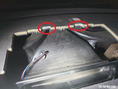
20210722_015917_lq.jpg (35.29 KiB) Viewed 2584 times
20210722_015942_lq.jpg
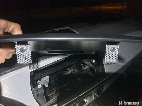
20210722_015942_lq.jpg (24.71 KiB) Viewed 2584 times
20210722_020438_lq.jpg
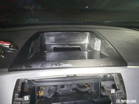
20210722_020438_lq.jpg (30.72 KiB) Viewed 2584 times
To have 100% perfect view you can cut with dremmel and polish (maybe also paint) front lip of monitor plate, but I am perfectly fine with current look.

Original wiring from X3 is plug and play. Of course before connecting I double checked with spec of Z4 connector and double checked location of power wires: battery, acc, illumination etc.

Current progress and challenges:
Canbus works perfectly - used option 85 "MW MINI FSTT 85" (option 65 BMW MINI was not available) in canbus setup menu.
1. Buttons on wheel are working perfectly and can be assinged for different options.
2. Rear camera turns on the monitor, after switching rear gear. Camera is not connected yet in my setup (ordered better AHD 1080p one), but Android catches rear gear signal and switches monitor to rear camera well.

Sound:
Sound generally is goob, but as unit is having amplifier and BMW is having amplifier there is double amplifier challenge. Ordered now Hi To Low 4 channel converter. Linear output can be used for the same purpose, but I decided to go for Hi Low first.
Ordered Radio Wire extension from the same store to do not cut orignal wire and to inject Hi Low converter in speaker outputs on extension wire.

Challenge with general volume. Currently volume is too independant. There is seperate volume for Nav, for BT, for Music/Radio etc. Volume difference is adjusted in engineering menu, but there is not kind of Master Volume. For example if volume is decreased for Radio, Nav continues to operate on its own volume and can be adjusted by volume button only in the moment NAV speaks. I need to find good app to handle it.

Video. Rear camera is good as mentioned. AHD 1080p supported. Not installed yet.
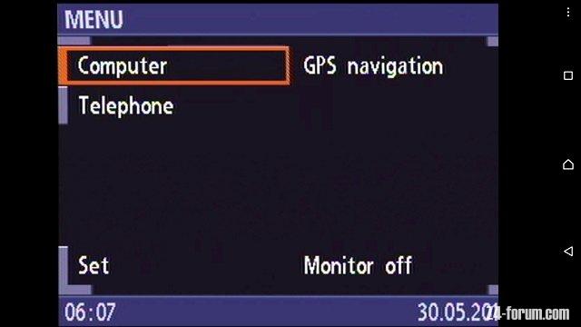
CVBS In is not as expected (to display board computer menu - not really reuqired, but let it be). Probaly its in PAL format. I am reusing Ambery device + LM1881 used in previous Android tabled integration described in the previous pages of this forum. Simple NTSC/PAL video screen for 10EUR worked perfectly with this signal.
Previous setup OK (EasyCap utv007):
BMW_CID_expected_easyCap_utv007_NTSC_lq.jpg
BMW_CID_expected_easyCap_utv007_NTSC_lq.jpg (20.73 KiB) Viewed 2584 times
Current one:
BMW_CID_v1_pro_cvbs_in_lq.jpg
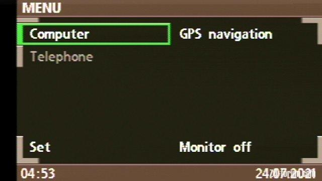
BMW_CID_v1_pro_cvbs_in_lq.jpg (21.96 KiB) Viewed 2584 times
Ordered PAL NTSC mini converter from Aliexpress to fix this, hope it will work.

Software:
Root access ok.
Challenges with original firmware, for example unit resets some settings and main screen after changing value in engineering menu etc. This is reported to manufacturer. Hope it will be resolved soon.

Summary:
New Android refreshed car for -10years. Its really nice to have fast operating Android onboard with 9" screen, good Nav (Waze), Youtube, Spotify, Internet etc. There are pending challenges but 6/128Gb Android 10 hardware is good starting point.
20210724_051939_lq.jpg
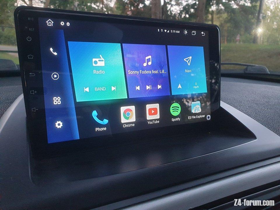
20210724_051939_lq.jpg (106.12 KiB) Viewed 2584 times
20210724_051925_lq.jpg
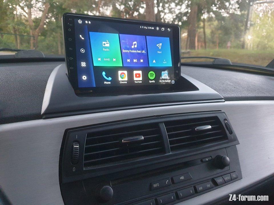
20210724_051925_lq.jpg (101.52 KiB) Viewed 2584 times
Current Costs:
Junsun V1 Pro 295EUR
1080p AHD cam 24EUR
Hi Low coverter 4ch 11EUR
Radio Extension Wire 4EUR
NTSC<-->PAL coverter 8EUR

Raben
Newbie
Newbie
Posts: 3
Joined: Fri Aug 06, 2021 4:42 am

E85 / E86 BMW Z4 – Android tablet integration

Post by Raben » Thu Feb 03, 2022 10:00 pm

Why are the images on page 6 lost?

Raben
Newbie
Newbie
Posts: 3
Joined: Fri Aug 06, 2021 4:42 am

E85 / E86 BMW Z4 – Android tablet integration

Post by Raben » Fri Feb 04, 2022 11:45 am

Hi js_online can you help me get the images of your old post. We are about to realize this but I please need some of your image to understand.

Trianta
Newbie
Newbie
Posts: 1
Joined: Sun Nov 27, 2022 1:50 pm

E85 / E86 BMW Z4 – Android tablet integration

Post by Trianta » Sun Nov 27, 2022 1:54 pm

LCDsizes.jpg
LCDsizes.jpg (74.07 KiB) Viewed 1177 times
Hello,
Anyone have a new idea for implementation?
Which newer phones can be installed?

Mojito
Member
Member
Posts: 199
Joined: Sat May 23, 2020 12:58 pm

E85 / E86 BMW Z4 – Android tablet integration

Post by Mojito » Sat Nov 11, 2023 6:32 pm

Not exactly Android Tablet integration, but someone suggested I should post a link here to my thread on 'Updating OEM Sat Nav whilst retaining 'Pop Up' functionality. I guess it's relevant and my thread is posted under E85 discussion where no one will ever find it :)
viewtopic.php?t=142096
E85 3.0i SE Sterling Grey, 2004
E89 20i SDrive M Sport - Mineral Grey - Sold

Raben
Newbie
Newbie
Posts: 3
Joined: Fri Aug 06, 2021 4:42 am

E85 / E86 BMW Z4 – Android tablet integration

Post by Raben » Sun Nov 12, 2023 12:06 am

I found VioVox 6214D 10.25" Android Touchscreen ready for E85. Has anybody experience with it?

Post Reply