DIY Brake Cooling.
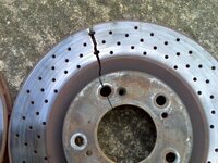
A number of BMW owners complain about their OEM brakes suffering from brake-fade when they take their cars on track. The problem is unlikely to be out-and-out stopping power of the brakes; instead, it is more likely to be the "duty cycle" between hard braking events is too short to allow sufficient cooling, so that the brakes, pads and fluid become progressively hotter, until they eventually exceed maximum operating temperature. Many owners feel that the only solution is to upgrade to a Big Brake kit (BBK), but these are expensive and can cost upwards of £1.6k for a well-known brand for the front alone. However there is a very cheap alternative, and that is the provision of brake cooling ducts which feeds cold air directly to the OEM brakes, so that there is a stream of cold air being fed to the brake hardware whilst the car is moving so that the temperature of the brakes will run much lower than would otherwise occur. In this way, the brakes are unlikely to overheat and cause brake-fade.
As far as I am aware, there are no aftermarket brake cooling kits, so I have devised a DIY method of brake cooling which can be made for less than £40. I have previously made a DIY brake cooling set up for my Z3 M Coupe, and this DIY set-up for the Z4MC is based on the method I've used for the M Coupe.
The first requirement is a source of cold air which can be forced through ducting whilst the car is in motion. From my datalogging of the Z4MC's air intake system, I know that all area behind the grilles and in front of the radiators receives air under "ram pressure", which will force air through ducting with inlets located in this part of the car. I have examined the structure of the car and discovered 2 places where inlets can be ideally located, with no need to cut holes in the front bumper.
You need to safely lift the car and place on axle stands under the 2 side jacking points and remove the front undertray (8mm socket and Phillips screwdriver required). Once underneath the engine bay, you will see a small plastic shroud at the bottom of the radiator on each side. If you cut a hole in both of these shrouds, then you have access into the area in front of the radiators, but behind the blanked-off section of the lower radiator grille. The fact that there is no forwards direct line of sight through the holes that you cut will NOT stop this acting as a source of ram-air (similar situation exists for the OEM air-intake).
The photo below shows the position on the right side where access to the front of the car to receive cold air under ram pressure.
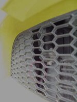
The shroud on the right side with a hole cut through showing the blanked off section of the lower front radiator grille.
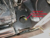
A small piece of ducting has been positioned in the hole in the shroud to show the connection to the front of the car.
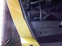
For my inlets, as an inveterate hoarder of stuff (just in case it might come in handy!), I already had a few sink outlets, which were just the right size to fit and install in the holes in the shrouds besides the radiator, so I cut holes of the right size to fit the sink outlets. Before I fitted them, I cut out the "star-shaped" centres, so that there was just one hole for my inlet.
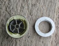
The sink outlet before cutting the "star-shaped" centre with the backing nut.
I intended to fit 2" internal diameter flexible hosing onto the ends of my inlets, but the threaded part of the inlets was a little too small, so I cut off 2" length of 2" diameter aluminium pipe (also in my hoard!) to fit as a sleeve over the threads, and attached the ducting to the aluminium pipe with a stainless steel jubilee clip. To get a tight "push-fit" connection, I needed to grind the screw-thread a little.
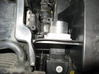
It is much easier to install the ducting on the right hand side, because on the left side, there are 2 pipes to the oil cooler, but I found it was possible to cut the hole in the shroud on the left with a Dremel after ensuring that I had located the best place to centre the inlet.
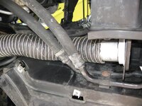
Once the holes had been cut and the inlets screwed in place, I could then attach both lengths of ducting on their sleeves, directly onto the inlets with a push-fit to secure. For ducting to be successful, it needs to be just the right extended length when the wheels are turned to maximum lock. I cut my initial lengths of ducting to 1metre per side. For the outlets of the brake ducting, I didn't want to cut the OEM dust-shield, especially since it already has vents in the front section, which I presume BMW had created to function for cooling already. So, I identified that the best place to site the outlets is just in front of the brake calipers, behind the damper, because there is an open space there, which is not covered by the dust shield. I experimented with various ways of routing the ducting to my chosen outlet point with lock-to-lock turning and found that the best route was essentially taking the outside path of the arms of the front ARB. The ducting needs to be tied with cable ties to the Anti-roll bar, just to the outside of the ARB bush and once the length of the ducting had been adjusted for lock-to-lock movement it can be securely fastened with more cable ties to the bottom of the damper, using the damper brackets as points of restraint, after the oulets have been attached to the ducting. The ducting fits between the damper and the drop link, and although there's not a lot of clearance. if the ducting is properly restrained, it makes no contact with any of the parts under movement and does not rub against the tyres.
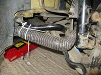
For my outlets, I have again used 2" diameter aluminium tube which required cutting to approximately 4" length and shaping so that the tubing would lie right up against the brake caliper and front damper, so that the outlet is right above the opening to the centre of the brakes.
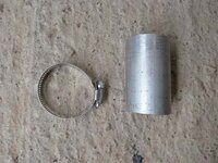
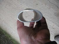
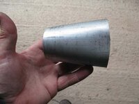
For the best fit of the aluminium oulet, the end needs to be cut at angle so that the oulet sits as close as possible to the damper leg and is pressed against the brake caliper and fits as flush as possible against the face of the brake bracketry. Once the outlet had been cut and shaped to the required fit, it was attached to the ducting with a jubilee clip, so that there was no twisting of the ducting when the aluminium outlet was properly in position. The outlet and the ducting are then attached to the damper using cable ties wrapped through the brackets on the damper as points of restraint.
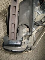
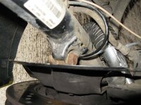
When the ducting is properly adjusted so that it is at full extension with no tension at maximum inward turning, the ducting should lie between the damper and the drop link to the ARB, with no pinching and with no contact with the wheel and tyre. On opposite lock, the ducting recoils and should make no contact with any part to do damage.
In the photographs I've used 300mm X 4.8mm nylon cable ties whilst experimenting, but for final use I will use 300mm X 7.6mm and on my Z3 M Coupe I've found that these will withstand any heat created by the brakes.
Stainless steel jubilee clips can be bought from ebay (require 4 of 50-70mm adjustment) as can flexible neoprene ducting (ebay search under "brake ducting") and 2" aluminium tube/pipe (1mm wall is suitable). Flexible ducting 51mm (2") is the optimum size that will work using the route which I have described; any larger ducting will pinch or require a reduction in lock-to-lock wheel turning which would severely increase the turning circle.
The Z4MC has a jacking-point in the centre of the car which is useful to lift the car so that it can be rested on 2 axle stands positioned on either side of the car on the side jacking-points.
In order to be able to easily move the wheel hubs by hand from lock-to-lock whilst working on them, first insert the ignition key and turn it to undo the steering lock, once this has been done, turn the key to OFF but leave it in the ignition and you can then press against the brake discs to turn the hubs to check for fitting throughout the fabrication and installation of the brake ducting.
A number of BMW owners complain about their OEM brakes suffering from brake-fade when they take their cars on track. The problem is unlikely to be out-and-out stopping power of the brakes; instead, it is more likely to be the "duty cycle" between hard braking events is too short to allow sufficient cooling, so that the brakes, pads and fluid become progressively hotter, until they eventually exceed maximum operating temperature. Many owners feel that the only solution is to upgrade to a Big Brake kit (BBK), but these are expensive and can cost upwards of £1.6k for a well-known brand for the front alone. However there is a very cheap alternative, and that is the provision of brake cooling ducts which feeds cold air directly to the OEM brakes, so that there is a stream of cold air being fed to the brake hardware whilst the car is moving so that the temperature of the brakes will run much lower than would otherwise occur. In this way, the brakes are unlikely to overheat and cause brake-fade.
As far as I am aware, there are no aftermarket brake cooling kits, so I have devised a DIY method of brake cooling which can be made for less than £40. I have previously made a DIY brake cooling set up for my Z3 M Coupe, and this DIY set-up for the Z4MC is based on the method I've used for the M Coupe.
The first requirement is a source of cold air which can be forced through ducting whilst the car is in motion. From my datalogging of the Z4MC's air intake system, I know that all area behind the grilles and in front of the radiators receives air under "ram pressure", which will force air through ducting with inlets located in this part of the car. I have examined the structure of the car and discovered 2 places where inlets can be ideally located, with no need to cut holes in the front bumper.
You need to safely lift the car and place on axle stands under the 2 side jacking points and remove the front undertray (8mm socket and Phillips screwdriver required). Once underneath the engine bay, you will see a small plastic shroud at the bottom of the radiator on each side. If you cut a hole in both of these shrouds, then you have access into the area in front of the radiators, but behind the blanked-off section of the lower radiator grille. The fact that there is no forwards direct line of sight through the holes that you cut will NOT stop this acting as a source of ram-air (similar situation exists for the OEM air-intake).
The photo below shows the position on the right side where access to the front of the car to receive cold air under ram pressure.

The shroud on the right side with a hole cut through showing the blanked off section of the lower front radiator grille.

A small piece of ducting has been positioned in the hole in the shroud to show the connection to the front of the car.

For my inlets, as an inveterate hoarder of stuff (just in case it might come in handy!), I already had a few sink outlets, which were just the right size to fit and install in the holes in the shrouds besides the radiator, so I cut holes of the right size to fit the sink outlets. Before I fitted them, I cut out the "star-shaped" centres, so that there was just one hole for my inlet.
The sink outlet before cutting the "star-shaped" centre with the backing nut.

I intended to fit 2" internal diameter flexible hosing onto the ends of my inlets, but the threaded part of the inlets was a little too small, so I cut off 2" length of 2" diameter aluminium pipe (also in my hoard!) to fit as a sleeve over the threads, and attached the ducting to the aluminium pipe with a stainless steel jubilee clip. To get a tight "push-fit" connection, I needed to grind the screw-thread a little.

It is much easier to install the ducting on the right hand side, because on the left side, there are 2 pipes to the oil cooler, but I found it was possible to cut the hole in the shroud on the left with a Dremel after ensuring that I had located the best place to centre the inlet.

Once the holes had been cut and the inlets screwed in place, I could then attach both lengths of ducting on their sleeves, directly onto the inlets with a push-fit to secure. For ducting to be successful, it needs to be just the right extended length when the wheels are turned to maximum lock. I cut my initial lengths of ducting to 1metre per side. For the outlets of the brake ducting, I didn't want to cut the OEM dust-shield, especially since it already has vents in the front section, which I presume BMW had created to function for cooling already. So, I identified that the best place to site the outlets is just in front of the brake calipers, behind the damper, because there is an open space there, which is not covered by the dust shield. I experimented with various ways of routing the ducting to my chosen outlet point with lock-to-lock turning and found that the best route was essentially taking the outside path of the arms of the front ARB. The ducting needs to be tied with cable ties to the Anti-roll bar, just to the outside of the ARB bush and once the length of the ducting had been adjusted for lock-to-lock movement it can be securely fastened with more cable ties to the bottom of the damper, using the damper brackets as points of restraint, after the oulets have been attached to the ducting. The ducting fits between the damper and the drop link, and although there's not a lot of clearance. if the ducting is properly restrained, it makes no contact with any of the parts under movement and does not rub against the tyres.

For my outlets, I have again used 2" diameter aluminium tube which required cutting to approximately 4" length and shaping so that the tubing would lie right up against the brake caliper and front damper, so that the outlet is right above the opening to the centre of the brakes.


For the best fit of the aluminium oulet, the end needs to be cut at angle so that the oulet sits as close as possible to the damper leg and is pressed against the brake caliper and fits as flush as possible against the face of the brake bracketry. Once the outlet had been cut and shaped to the required fit, it was attached to the ducting with a jubilee clip, so that there was no twisting of the ducting when the aluminium outlet was properly in position. The outlet and the ducting are then attached to the damper using cable ties wrapped through the brackets on the damper as points of restraint.


When the ducting is properly adjusted so that it is at full extension with no tension at maximum inward turning, the ducting should lie between the damper and the drop link to the ARB, with no pinching and with no contact with the wheel and tyre. On opposite lock, the ducting recoils and should make no contact with any part to do damage.
In the photographs I've used 300mm X 4.8mm nylon cable ties whilst experimenting, but for final use I will use 300mm X 7.6mm and on my Z3 M Coupe I've found that these will withstand any heat created by the brakes.
Stainless steel jubilee clips can be bought from ebay (require 4 of 50-70mm adjustment) as can flexible neoprene ducting (ebay search under "brake ducting") and 2" aluminium tube/pipe (1mm wall is suitable). Flexible ducting 51mm (2") is the optimum size that will work using the route which I have described; any larger ducting will pinch or require a reduction in lock-to-lock wheel turning which would severely increase the turning circle.
The Z4MC has a jacking-point in the centre of the car which is useful to lift the car so that it can be rested on 2 axle stands positioned on either side of the car on the side jacking-points.
In order to be able to easily move the wheel hubs by hand from lock-to-lock whilst working on them, first insert the ignition key and turn it to undo the steering lock, once this has been done, turn the key to OFF but leave it in the ignition and you can then press against the brake discs to turn the hubs to check for fitting throughout the fabrication and installation of the brake ducting.
