

Code: Select all
BMW E85/E86 Business Radio Pin Outs
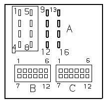
Pin assignments at black plug connector X18805 pins 1-8 (A)
Pin assignments at black plug connector X18126 pins 9-16 (A)
Pin Type Description / Signal type / Connection / Area mm^2 / Colour/Tracer-Option Level
1 A Signal, AF radio, rear right + Amplifier or Speaker 0.75 Blu/Viol Basic (Blu/Blk Hi-Fi)[not used Carver]
2 A Signal, AF radio, front right + Amplifier or Speaker 0.75 Blu/Red
3 A Signal, terminal 50 via vehicle immoblizer Amplifier or Speaker 0.75 Yell/Red
4 A Signal, AF radio, rear left + Amplifier or Speaker 0.75 Yell/Viol Basic (Yell/Blk Hi-Fi)[not used Carver]
5 A Signal, AF radio, rear right - Amplifier or Speaker 0.75 Blu/Grn Basic (Brn/Org Hi-Fi)[not used Carver]
6 A Signal, AF radio, front right - Amplifier or Speaker 0.75 Blu/Brn Basic (Brn/Org Hi-Fi Carver)
7 A Signal, AF radio, front left - Amplifier or Speaker 0.75 Yell/Brn Basic (Brn/Org Hi-Fi Carver)
8 A Signal, AF radio, rear left - Amplifier or Speaker 0.75 Yell/Grn Basic (Brn/Org Hi-Fi)[not used Carver]
9 E/A K-bus signal K-bus connector 0.5 Wht/Red/Yell
10 E Telephone mute circuit Cellular telephone 0.35 Wht/Brn
11 E Signal Telephone on Cellular telephone 0.35 Wht/Grn
12 M Ground Ground point 2.5 Brn
13 E Aerial switching signal Aerial amplifier or aerial diversity 0.5 Wht
14 E Activation, left bi-xenon headlight Light switch cluster 0.5 Grn/Red
15 E Terminal 30 Fuse F50 Unsitched power 2.5 Red/Yell
16 E Terminal R Fuse F47 Switched power 0.75 Viol/Wht
Pin assignments at beige plug connector X13321 (B)
Pin Type Description / Signal type / Connection / Area mm^2 / Colour/Tracer
1 Not used {headphones left}
2 E Signal, CD changer AF -, common CD changer 0.5 Wht/Brn
3 Not used {headphones Common}
4 Not used {VCR right}
5 Not used {VCR left}
6 Not used {VCR common}
7 Not used {headphones right}
8 E Signal, CD changer AF +, left CD changer 0.5 Wht/Red
9 E Signal, CD changer AF +, right CD changer 0.5 Wht/Blu
10 Not used {TV right}
11 Not used {TV left}
12 Not used {TV common}
Pin assignments at grey plug connector X13598 (C)
Pin Type Description / Signal type / Connection / Area mm^2 / Colour/Tracer
1 Not used {tape left+}
2 Not used {tape left-}
3 E AF signal, left AV socket 0.35 Blk
4 E AF signal, right AV socket 0.35 Yell
5 A Navigation signal Positive activation Navigation system or Video module 0.5 Blu/Red
6 E Signal, telephone AF + Cellular telephone 0.75 Blk/Wht
7 Not used {tape right+}
8 Not used {tape right-}
9 Not used (Radio Nav Only 0.5 Wht/Grn)
10 M Shield AV socket
11 A Navigation signal Negative activation Navigation system or Video module 0.5 Yell/Brn
12 E Signal, terminal 50 via vehicle immoblizer Cellular telephone 0.75 Blk/Brn
Assignments at cable shoe X13342 (Not shown in diagram)
Pin Type Description / Signal type Connection
1 A Signal, aerial reception Aerial amplifier or aerial diversity
{Curly braces = Obsolete, for info only}
Max
mm^2 AWG Amps
0.35 22 3
0.5 20 5
0.75 18 7.5
1.0 17 10
2.5 13 15
4.0 11 20
Search terms: business radio pin outs out pinouts pinout assignment navigation auxiliary input wiring color area output signal CD changer compact disc plug front rear speaker amp amplifier phone telephone