How to modify your CDV (Clutch Delay Valve)
Posted: Thu Sep 06, 2007 8:49 am
This is the one you have all been waiting for.
I have posted this How to Do in this section to ensure maximum exposure.
This valve is from a non M Z4, although I am assuming the process would be the same, if someone want to send me a M valve, I will test.
Although this is a simple process I do not accept any responsibility for any damage to you, your vehicle or any third party if you carry out this procedure.
I would also like a couple of our members to validate this process. I know our leader has a spare one, or at least one that requires modification.
I would suggest that you do this process on a spare valve just incase you do run into trouble. There are enough Z4 owners out there that have changed this part so hopefully you could find someone who will either give you their old one or loan you one until you take yours off.
If however you wish to purchase one from your dealer the price I obtained is £7.79 + vat. There is no stock in this country so delivery would be 3-4 days.
Unfortunately, I wasn’t present when I got my guy to remove this as I thought it was going to be harder than it was and therefore left him to it. But once I have changed mine, I do intend to carry out this procedure, after which I will happily donate. I would however suggest that all owners generally modify their own to prevent any problems with comeback etc.
This is a simple process that requires no special tools other than a hammer and two drills bits of 3.5mm and 9mm NO DRILLING IS INVOLVED. If you have ever replaced a wheel bearing this should be a simple procedure.

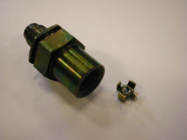
Fig1. shows a sectional view of the valve, the device and principal are both simple. When you depress the clutch the piston (C) moves towards the insert (B) due to hydraulic pressure which allow hydraulic fluid around the piston due to its design, when you remove your foot from the clutch the hydraulic pressure forces the piston back which forces the hydraulic fluid through the 1.5mm diameter hole. There is no spring in the valve; the force of the hydraulic fluid alone moves the piston to its required position.
The insert does two jobs, to retain the piston, and locate and seal the rigid hydraulic pipe. As it located on a step when the insert is refitted it will be in its original location. The insert is retained only by the slight interference fit with the body so is easily removed and reinserted. The slight interference is confirmed by the fact the piston has retained most of its shape after removal, if this had required a lot of force the piston would be have deformed more before the insert was removed and would probably be flat.
The process:
Insert the 3.5mm drill bit into the end with the male thread (small bore) ensuring you insert the flat end of the drill. If you insert the pointed end you will probably damage the piston and it will then be impossible to remove successfully.
It is possible to use any cylindrical object that fits the bore with a snug fit and has at flat end to locate against the piston. A screwdriver with the end ground of may also work.
By gently tapping the drill with a hammer will push the piston and insert out of the bottom. Be aware that this will probably damage you drill bit. It would be advisable to hold the valve in a vice if possible, it does not need to be done up tight, as the hex flats will locate above the jaws and prevent movement. Doing this will allow the piston and insert free exit from the body.
Once you have removed the piston you then use the 9mm drill bit again with the blunt end against the insert and tap back into place. Ensure you insert the valve the correct way with the chamfered bore facing out. It maybe easier to use a socket if the outside diameter is around 9mm as this will have a flat end top and bottom, but ensure it will fit inside the bore before attempting to refit. Again you need to use something like this for two reasons; one is so the flat bottom locates on the flats of the insert to prevent damage to the sealing chamfer, and also to ensure the insert is inserted squarely to prevent damage to the threads.
Once you have replaced the insert you are ready to fit to your car and enjoy the smoother clutch operation this procedure gives.
Apologies for grammatical errors, spelling mistakes etc. and I look forward to your feedback.
Steve
I have posted this How to Do in this section to ensure maximum exposure.
This valve is from a non M Z4, although I am assuming the process would be the same, if someone want to send me a M valve, I will test.
Although this is a simple process I do not accept any responsibility for any damage to you, your vehicle or any third party if you carry out this procedure.
I would also like a couple of our members to validate this process. I know our leader has a spare one, or at least one that requires modification.
I would suggest that you do this process on a spare valve just incase you do run into trouble. There are enough Z4 owners out there that have changed this part so hopefully you could find someone who will either give you their old one or loan you one until you take yours off.
If however you wish to purchase one from your dealer the price I obtained is £7.79 + vat. There is no stock in this country so delivery would be 3-4 days.
Unfortunately, I wasn’t present when I got my guy to remove this as I thought it was going to be harder than it was and therefore left him to it. But once I have changed mine, I do intend to carry out this procedure, after which I will happily donate. I would however suggest that all owners generally modify their own to prevent any problems with comeback etc.
This is a simple process that requires no special tools other than a hammer and two drills bits of 3.5mm and 9mm NO DRILLING IS INVOLVED. If you have ever replaced a wheel bearing this should be a simple procedure.
Fig1. shows a sectional view of the valve, the device and principal are both simple. When you depress the clutch the piston (C) moves towards the insert (B) due to hydraulic pressure which allow hydraulic fluid around the piston due to its design, when you remove your foot from the clutch the hydraulic pressure forces the piston back which forces the hydraulic fluid through the 1.5mm diameter hole. There is no spring in the valve; the force of the hydraulic fluid alone moves the piston to its required position.
The insert does two jobs, to retain the piston, and locate and seal the rigid hydraulic pipe. As it located on a step when the insert is refitted it will be in its original location. The insert is retained only by the slight interference fit with the body so is easily removed and reinserted. The slight interference is confirmed by the fact the piston has retained most of its shape after removal, if this had required a lot of force the piston would be have deformed more before the insert was removed and would probably be flat.
The process:
Insert the 3.5mm drill bit into the end with the male thread (small bore) ensuring you insert the flat end of the drill. If you insert the pointed end you will probably damage the piston and it will then be impossible to remove successfully.
It is possible to use any cylindrical object that fits the bore with a snug fit and has at flat end to locate against the piston. A screwdriver with the end ground of may also work.
By gently tapping the drill with a hammer will push the piston and insert out of the bottom. Be aware that this will probably damage you drill bit. It would be advisable to hold the valve in a vice if possible, it does not need to be done up tight, as the hex flats will locate above the jaws and prevent movement. Doing this will allow the piston and insert free exit from the body.
Once you have removed the piston you then use the 9mm drill bit again with the blunt end against the insert and tap back into place. Ensure you insert the valve the correct way with the chamfered bore facing out. It maybe easier to use a socket if the outside diameter is around 9mm as this will have a flat end top and bottom, but ensure it will fit inside the bore before attempting to refit. Again you need to use something like this for two reasons; one is so the flat bottom locates on the flats of the insert to prevent damage to the sealing chamfer, and also to ensure the insert is inserted squarely to prevent damage to the threads.
Once you have replaced the insert you are ready to fit to your car and enjoy the smoother clutch operation this procedure gives.
Apologies for grammatical errors, spelling mistakes etc. and I look forward to your feedback.
Steve